pzgr40
Well-Known Member
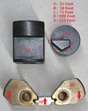
Cutaway model of an American AN (Army Navy) Mk230 Mk-1 Hydrostatic tail fuze from 1944, as used in the 325 Lbs AN-Mk.53 Mod.1 and the 350 Lbs AN-Mk.54 Mod.1 depth charges. The fuze is hydrostatic (works on water pressure) and is adjustable to five different depths; 25, 50, 75, 100 and 125 feet depth.
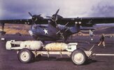
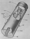
The Mk.54 depth charge contained 113.4 kg of Torpex, and was thus almost twice as powerful as previous -TNT- filled- depth charges. A Mk.54 depth charge detonated 18 feet (5.5 meters) from the hull of a submarine resulted in guaranteed destruction.
Both depth charges were also suitable for use against land targets when equipped with a nose fuze. When used against submarines, only the hydrostatic tail fuze was used. The fuze was also screwed into the back of GP aircraft bombs, so they could serve as depth charges.
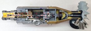
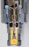
When the aircraft drops the depth charge with the Mk230 Mk-1 Hydrostatic tail fuze, the arming wire is pulled out of the impeller (1), causing it to rotate in the air stream. The impeller drives the vane shaft (2), which in turn drives the pinion gear (3). The pinion idler gearwheels (4) have the same number of teeth; the fixed upper gear on top of the pinion gear has 22 teeth and the movable lower gear (5) under the pinion gear has 23 teeth. This ensures that the arming bolt (6) makes one revolution for every 23 revolutions of the pinion gear. This causes the arming nut (7) to slowly move upwards. On the underside of the arming nut (7) there are two pins (8) that protrude through the detent retaining cup (9) into the housing (10) for the two detent pins (11). When the two pins (8) of the arming nut (7) have been pulled out of the housing (10) of the detent pins, the arming nut has been turned to the highest possible position and the two pins (8) only protrude into the detent retaining cup cup (9) which now begins to turn. In the side of the detent retaining cup there are two recesses placed opposite each other, and when the cup has been turned far enough, the two detent pins (11) will fall into the recesses and be pushed outwards by their spring.
The fuze is now -after falling approximately 400 feet of air travel (appr. 120 metres)- fully armed because the two detent pins (11) that are placed in a groove in the depth spring stem nut (12) have moved outwards.
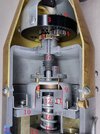
In the side of the igniter body is a selector (13) with the depth settings. The depth setting mechanism is visible in photo 04. By turning the knob on the outside of the fuze body, one of the five surfaces on the selector (13) is placed under the green line of the depth adjusting sleeve (14) for the depth spring (15), whereby the depth spring is tensioned to a certain extent between the adjusting sleeve (14) and the depth spring stem nut (12). The depth spring stem (16) to which the nut (12) is attached is screwed over the piston stem (17). The adjusting sleeve is placed in the housing (18), which only allows a linear movement of the adjusting sleeve (14) - forwards and backwards. However, the adjusting sleeve is not connected to the depth spring stem or the piston stem. A brass bellow (19) is soldered to the piston stem (17) with the lower side, and soldered to a brass flange (20) on the other side. As soon as the depth charge disappears under water, the fuze body starts filling with water through two opposite holes (21), and the water flows through four holes in the housing (18) into the bellow. The water pressure will stretch the bellow (19) thus pushing the piston stem (17) downward, until the moment that the six balls (22) that fixate the piston detonator (23) fall into the internally widened part of the piston stem (17), and release the detonator piston( 23). The firing spring (24) above the piston detonator will push it downwards, whereby the detonator moves into the fixed firing pin (25) and detonates. The flame from the detonator travels through the small hole in the side of the piston detonator into the lead in charge (26) and the relay pellets (27) that ignite the booster charge (28), after which the depth charge detonates.
The only question that remains is… what is the purpose of the two inertia counter balance weights (29), which are connected to each other by an aluminium lock plate (30) placed between the depth spring stem (16) and the piston stem (17)?
Because the Mk53 and Mk54 depth charges have a flat nose, the bomb will brake quite abruptly upon impact with the waves, causing the inertia to 'throw' the loose parts in the fuze quite abruptly forward; because the depth spring stem (16) and the brass piston stem (17) connected to it, containing the steel piston detonator (23) are quite heavy, and are only held back by the depth -compression- spring (15), there is a risk that with a shallow setting - weak spring setting- the inertia of these parts will exceed the spring force when they are thrown forward, causing the depth charge to detonate upon impact with the waves. The two inertia counter balance weights (29) -both on a shaft (31) - will also be thrown forward upon impact and will temporarily (until the inertia effect has stopped) push the combination of the depth spring stem (16), the brass piston stem (17) housing the piston detonator backwards with a force equal to the inertia effect of the the depth spring stem (16), brass piston stem (17) and piston detonator. This creates a momentary balance that prevents the fuze from being activated prematurely.
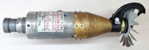
Length of fuze (w/o arming wire guidance piece) : 389 mm (15,31 inch).
Diameter fuze body : 85,5 mm (3,36 inch).
Diameter impeller : 133 mm (5,23 inch).
Regards, DJH
The Mk.54 depth charge contained 113.4 kg of Torpex, and was thus almost twice as powerful as previous -TNT- filled- depth charges. A Mk.54 depth charge detonated 18 feet (5.5 meters) from the hull of a submarine resulted in guaranteed destruction.
Both depth charges were also suitable for use against land targets when equipped with a nose fuze. When used against submarines, only the hydrostatic tail fuze was used. The fuze was also screwed into the back of GP aircraft bombs, so they could serve as depth charges.
When the aircraft drops the depth charge with the Mk230 Mk-1 Hydrostatic tail fuze, the arming wire is pulled out of the impeller (1), causing it to rotate in the air stream. The impeller drives the vane shaft (2), which in turn drives the pinion gear (3). The pinion idler gearwheels (4) have the same number of teeth; the fixed upper gear on top of the pinion gear has 22 teeth and the movable lower gear (5) under the pinion gear has 23 teeth. This ensures that the arming bolt (6) makes one revolution for every 23 revolutions of the pinion gear. This causes the arming nut (7) to slowly move upwards. On the underside of the arming nut (7) there are two pins (8) that protrude through the detent retaining cup (9) into the housing (10) for the two detent pins (11). When the two pins (8) of the arming nut (7) have been pulled out of the housing (10) of the detent pins, the arming nut has been turned to the highest possible position and the two pins (8) only protrude into the detent retaining cup cup (9) which now begins to turn. In the side of the detent retaining cup there are two recesses placed opposite each other, and when the cup has been turned far enough, the two detent pins (11) will fall into the recesses and be pushed outwards by their spring.
The fuze is now -after falling approximately 400 feet of air travel (appr. 120 metres)- fully armed because the two detent pins (11) that are placed in a groove in the depth spring stem nut (12) have moved outwards.
In the side of the igniter body is a selector (13) with the depth settings. The depth setting mechanism is visible in photo 04. By turning the knob on the outside of the fuze body, one of the five surfaces on the selector (13) is placed under the green line of the depth adjusting sleeve (14) for the depth spring (15), whereby the depth spring is tensioned to a certain extent between the adjusting sleeve (14) and the depth spring stem nut (12). The depth spring stem (16) to which the nut (12) is attached is screwed over the piston stem (17). The adjusting sleeve is placed in the housing (18), which only allows a linear movement of the adjusting sleeve (14) - forwards and backwards. However, the adjusting sleeve is not connected to the depth spring stem or the piston stem. A brass bellow (19) is soldered to the piston stem (17) with the lower side, and soldered to a brass flange (20) on the other side. As soon as the depth charge disappears under water, the fuze body starts filling with water through two opposite holes (21), and the water flows through four holes in the housing (18) into the bellow. The water pressure will stretch the bellow (19) thus pushing the piston stem (17) downward, until the moment that the six balls (22) that fixate the piston detonator (23) fall into the internally widened part of the piston stem (17), and release the detonator piston( 23). The firing spring (24) above the piston detonator will push it downwards, whereby the detonator moves into the fixed firing pin (25) and detonates. The flame from the detonator travels through the small hole in the side of the piston detonator into the lead in charge (26) and the relay pellets (27) that ignite the booster charge (28), after which the depth charge detonates.
The only question that remains is… what is the purpose of the two inertia counter balance weights (29), which are connected to each other by an aluminium lock plate (30) placed between the depth spring stem (16) and the piston stem (17)?
Because the Mk53 and Mk54 depth charges have a flat nose, the bomb will brake quite abruptly upon impact with the waves, causing the inertia to 'throw' the loose parts in the fuze quite abruptly forward; because the depth spring stem (16) and the brass piston stem (17) connected to it, containing the steel piston detonator (23) are quite heavy, and are only held back by the depth -compression- spring (15), there is a risk that with a shallow setting - weak spring setting- the inertia of these parts will exceed the spring force when they are thrown forward, causing the depth charge to detonate upon impact with the waves. The two inertia counter balance weights (29) -both on a shaft (31) - will also be thrown forward upon impact and will temporarily (until the inertia effect has stopped) push the combination of the depth spring stem (16), the brass piston stem (17) housing the piston detonator backwards with a force equal to the inertia effect of the the depth spring stem (16), brass piston stem (17) and piston detonator. This creates a momentary balance that prevents the fuze from being activated prematurely.
Length of fuze (w/o arming wire guidance piece) : 389 mm (15,31 inch).
Diameter fuze body : 85,5 mm (3,36 inch).
Diameter impeller : 133 mm (5,23 inch).
Regards, DJH
Attachments
-
 01 - Hydrostatisc tail fuze AN-Mk 230 Mk1 cutaway model with numbers.jpg1.1 MB · Views: 62
 -
 02 - Hydrostatisc tail fuze AN-Mk 230 Mk1 backside.jpg1.2 MB · Views: 62
 -
 03 - Hydrostatisc tail fuze AN-Mk 230 Mk1 arming mechanism details.jpg1.9 MB · Views: 59
 -
 04 - Hydrostatisc tail fuze AN-Mk 230 Mk1 selector and counter balance weights.jpg1.1 MB · Views: 57
 -
 05 - Hydrostatisc tail fuze AN-Mk 230 Mk1detonator and booster details.jpg1.3 MB · Views: 54
 -
 06 - 350 Lbs depth charge AN-Mk 54 Mod-1.jpg86.5 KB · Views: 59
Last edited: