pzgr40
Well-Known Member
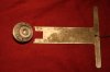
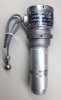
Cutaway model of a Russian AVT-E nose and tail fuze. The fuze is elctrically activated, after which the fuze is a mechanical activated allways fuze. The fuze in the picture is pictured in armed condition.
The fuze is 203mm long and the top part has a ø60mm diameter.
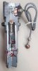
The fuze consists of three main parts; the top part (1), housing the electrically served arming part (2), the lower part (3) with the all ways fuze (4) and the pyrotecnic delay elements (5). Below that , the booster (6) is placed.
The fuze is screwed into the nose or base of a bomb and the electric connector ball (7) on the wire is placed into the electric connection piece of the bomb rack, closing the electric circuit. An electric firing cap (8) which –when electrically powered- ignites two delay pellets (9, yellow). When these are burned through, they ignite a explosive powered piston (10) which is fired into the direction of the centerline (red arrow). Due to the speed of the piston movement the horizontal arming pin (11, pict 02) is projected outward, locked by the cone shaped end of the hole.
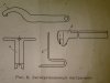
In the lower part of the fuze the allways fuze is placed. When the fuze is in safe condition, the arming piston (12) is in it’s lower position, locking the allways fuze in safe condition. The firing pin (13, light blue) is placed in the upper telescoped cilinder(14) of the all ways fuze, the firing (16) cap is placed in the lower telescoped cilinder (15) of the all ways fuze. A light pressure spring is placed between the upper and lower telescoped cilinders, keeping them apart when armed. When in safe position, the firing cap (16) is kept out of line by the firing pin protruding through the lower telescoped cylinder (15). When the fuze is armed the firing pin is retracted and the firing cap is pushed in the centerline by a light radial spring, and locked in position by a locking pin.
Below the allways fuze four radial holes are drilled in which a screw (18) is placed. By unscrewing one of the four screws a delay element (20) -or no delay (19)- is released.
The flame of the firing cap (16) or one of the delay elements ignites a boosting firing cap (21) that ignites the detonator (22), which ignites the booster (6). This will ignite the bomb.
Functioning:
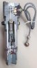
While the bomb is ejected the electric circuit is powered , causing the horizontal arming pin (11) to be pushed away after a short delay. This allows the arming piston to move upward and activate the allways fuze. The firing pin is retraced upward, the firing cap is placed in line and locked and the fuze is armed.
When the bomb lands on it’s noze or tail the firing pin cilinders is telescope in the firing cap cilinder or vica versa, when the bomb lands on it’s side the conical ends of the cilinders move sideways in the conical shaped inside of the fuze (23), forcing the firing cap and firing pin together.
FAB-1500 M54 General purpose
FAB-1500 M46 General purpose
FAB-250 M54 General purpose
FAB-250 SHN HE, Retarded, 275kg
FAB-500 M54 General purpose
FAB-500 M46 General purpose
FAB-500SH General purpose 500 Kg
Regards, DJH
The fuze is 203mm long and the top part has a ø60mm diameter.
The fuze consists of three main parts; the top part (1), housing the electrically served arming part (2), the lower part (3) with the all ways fuze (4) and the pyrotecnic delay elements (5). Below that , the booster (6) is placed.
The fuze is screwed into the nose or base of a bomb and the electric connector ball (7) on the wire is placed into the electric connection piece of the bomb rack, closing the electric circuit. An electric firing cap (8) which –when electrically powered- ignites two delay pellets (9, yellow). When these are burned through, they ignite a explosive powered piston (10) which is fired into the direction of the centerline (red arrow). Due to the speed of the piston movement the horizontal arming pin (11, pict 02) is projected outward, locked by the cone shaped end of the hole.
In the lower part of the fuze the allways fuze is placed. When the fuze is in safe condition, the arming piston (12) is in it’s lower position, locking the allways fuze in safe condition. The firing pin (13, light blue) is placed in the upper telescoped cilinder(14) of the all ways fuze, the firing (16) cap is placed in the lower telescoped cilinder (15) of the all ways fuze. A light pressure spring is placed between the upper and lower telescoped cilinders, keeping them apart when armed. When in safe position, the firing cap (16) is kept out of line by the firing pin protruding through the lower telescoped cylinder (15). When the fuze is armed the firing pin is retracted and the firing cap is pushed in the centerline by a light radial spring, and locked in position by a locking pin.
Below the allways fuze four radial holes are drilled in which a screw (18) is placed. By unscrewing one of the four screws a delay element (20) -or no delay (19)- is released.
The flame of the firing cap (16) or one of the delay elements ignites a boosting firing cap (21) that ignites the detonator (22), which ignites the booster (6). This will ignite the bomb.
Functioning:
While the bomb is ejected the electric circuit is powered , causing the horizontal arming pin (11) to be pushed away after a short delay. This allows the arming piston to move upward and activate the allways fuze. The firing pin is retraced upward, the firing cap is placed in line and locked and the fuze is armed.
When the bomb lands on it’s noze or tail the firing pin cilinders is telescope in the firing cap cilinder or vica versa, when the bomb lands on it’s side the conical ends of the cilinders move sideways in the conical shaped inside of the fuze (23), forcing the firing cap and firing pin together.
FAB-1500 M54 General purpose
FAB-1500 M46 General purpose
FAB-250 M54 General purpose
FAB-250 SHN HE, Retarded, 275kg
FAB-500 M54 General purpose
FAB-500 M46 General purpose
FAB-500SH General purpose 500 Kg
Regards, DJH
Attachments
Last edited: