pzgr40
Well-Known Member
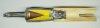
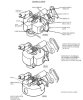
Cutaway model of a Mk-118 HEAT clusterbomb as used in the Rockeye CBU.
The CBU-99/B (A/B , B/B) houses 247 Mk-118 mod. 0 clusterbombs in the SUU-75/B (A/B , B/B) Clusterbomb body. The A/B and B/B series have minor variations. (CBU = Cluster Bomb Unit).
The CBU-100/B is nearly identical to the CBU-100(B) and the Mk-20 (Naval version), also housing 247 Mk-118 cluster bombs
The Mk-118 is an anti-armour clusterbomb, it has no anti-personnel function. Upon detonation the shaped charge will penetrate 190mm (7.48 inch) of steel, more than sufficient when hitting any armoured vehicle on top.
The Mk-118 Rockeye is composed of the following parts (nose to base);
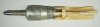
-The Piezo-electric impact nose fuze;
The nose fuze is a tapered stainless steel pipe, roll crimped over the stand-off nose piece below. On the inside a piezo-electric crystal is place below a stab detonator. Above the stab detonator a firing pin is placed in a striker. A shear washer keeps the firing pin fixated in it’s forward position. Upon impact with a hard object, the shear washer is sheared off by the striker moving inward, pushing the firing pin into the stab detonator. This pushes the housing of the stab detonator downward with force, applying pressure on the piezo-electric crystal that starts delivering current when under pressure.
-The stand-off nose piece;
A pressed sheet steel nose piece in the form of a pipe with a flange. The stand-off ensures the optimum distance between the red copper cone and the target, ensuring maximum penetration.
-The clusterbomb body;
A pressed sheet steel body, housing the red copped cone and the explosive charge of 181 grams Comp B. , either Octol 75/25. In the base of the explosive charge a 5,1 grams cylindrical Tetryl booster is placed, just above the lead in the base fuze.
The electric wire runs from the nose fuze to the base fuze through the explosive charge.
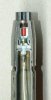
-The electro-mechanical base fuze (PIBD = Point Ignited Base Detonated);
A cast and machined Zamac (Alloy of Zinc , aluminium, Magnesium and Copper, used f.i for casting carburettors) fuze body. It houses the arming rotor which is connected to the rotor drive plate. The rotor is kept appr 90 degrees out of line with the lead in top of the fuze body. On the inside of the Rotor a channel is drilled , housing the electric detonator and a spring loaded electric contact. The rotor is kept in fixated position by a spring loaded pin in the base of the fuze. The pin is kept in forward position by two spring loaded detents that are centrifugally activated. Both detents are connected to the arming vane at 180 degrees each.
An impact inertia firing pin is placed in the longitudal direction of the fuze in a hole, just beside the arming rotor. The firing pin has a recess in the middle. A ridge is placed on one flat side of the rotor over 90 degrees. In safe position it fixates the impact inertia firing pin as the ridge falls in the recess of the firing pin, locking it from forward movement. Above the firing pin a stab detonator is placed. The firing pin and the stab detonator are kept apart by a creep spring.
The speed of the rotor is regulated by a camwheel with an escapement.
In top of the fuze housing, the lead is placed. This is a booster that is placed between the electric firing cap in the rotor and the Tetryl booster in the base of the explosive charge.
-The tail fin;
A white nylon tailfin with a sheet steel ring in top that is used to connect the tail to the tail to the body and lock up the base fuze.
Functioning of the Mk-118 clusterbomb:
Upon release from the CBU container the airstream makes the arming vane rotate. The two springloaded radial detents are thrown outward by the centrifugal force, allowing the spring loaded arming pin to move backward through the opening between the two detents.
With the arming pin removed the rotor is free to rotate 90 degrees into the centreline of the clusterbomb (armed position). The drive grommet –connected to the vane- rotates the rotor the first 40 degrees from safe into a partially armed position by means of a 0.9 seconds delay escapement governed camwheel. When the camwheel governed 40 degrees is expired, the rotor is further rotated into armed position by a friction drive on the drive grommet, rotating the arming rotor the full 90 degrees into armed position.
With the arming rotor in armed position the electric circuit with the nose fuze is closed.
When the arming rotor rotates, the ridge on the arming wheel is rotated out of the recess in the impact inertia firing pin, allowing the firing pin to move forward into the stab detonator upon impact.
The reason for an electric and mechanical fuzing system can easily be explained; upon hitting a hard target (steel, concrete) the nose fuze is initiated, activating the electric detonator in the base fuze, exploding the shaped charge.
If no hard target is hit (sand, earth) the nose probe of the clusterbomb digs in up to the flange, activating the impact inertia firing pin, activating the stab detonator. The flame of this stab detonator is passed to the electric detonator through a blow hole.
The creep spring between the impact inertia firing pin and the stab detonator enshures the fuze is not activated by foliage or leafs, but is sensitive enough to detonate the clusterbomb on impact with a target with enough resistance.
If the electric detonator in the base fuze is initiated by the nose fuze, this ignition is always faster than the ignition of the stab detonator by the impact inertia firing pin, so although both detonators (electric and stab) are initiated upon impact with a hard target, the electric detonator in the rotor will detonate the clusterbomb.
A sheet metal protective cover is placed around the base fuze. A small hole (window) is drilled in this cover i.w.o. the camwheel. The camwheel is partially painted red. If a red colour is visible through the window, the Mk-118 is armed.
Dimensions Mk-118:
Complete length : 343mm , (13,5")
Diameter tail : 57mm , (2,25")
Diameter Bomb body : 53mm , (2,1")
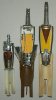
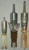
On the last pictures one can clearly see there is a “rockeye” type series, - from left to right-, the BLU-77B, the ISCB-1 and the Mk-118 Rockeye
Regards, DJH
The CBU-99/B (A/B , B/B) houses 247 Mk-118 mod. 0 clusterbombs in the SUU-75/B (A/B , B/B) Clusterbomb body. The A/B and B/B series have minor variations. (CBU = Cluster Bomb Unit).
The CBU-100/B is nearly identical to the CBU-100(B) and the Mk-20 (Naval version), also housing 247 Mk-118 cluster bombs
The Mk-118 is an anti-armour clusterbomb, it has no anti-personnel function. Upon detonation the shaped charge will penetrate 190mm (7.48 inch) of steel, more than sufficient when hitting any armoured vehicle on top.
The Mk-118 Rockeye is composed of the following parts (nose to base);
-The Piezo-electric impact nose fuze;
The nose fuze is a tapered stainless steel pipe, roll crimped over the stand-off nose piece below. On the inside a piezo-electric crystal is place below a stab detonator. Above the stab detonator a firing pin is placed in a striker. A shear washer keeps the firing pin fixated in it’s forward position. Upon impact with a hard object, the shear washer is sheared off by the striker moving inward, pushing the firing pin into the stab detonator. This pushes the housing of the stab detonator downward with force, applying pressure on the piezo-electric crystal that starts delivering current when under pressure.
-The stand-off nose piece;
A pressed sheet steel nose piece in the form of a pipe with a flange. The stand-off ensures the optimum distance between the red copper cone and the target, ensuring maximum penetration.
-The clusterbomb body;
A pressed sheet steel body, housing the red copped cone and the explosive charge of 181 grams Comp B. , either Octol 75/25. In the base of the explosive charge a 5,1 grams cylindrical Tetryl booster is placed, just above the lead in the base fuze.
The electric wire runs from the nose fuze to the base fuze through the explosive charge.
-The electro-mechanical base fuze (PIBD = Point Ignited Base Detonated);
A cast and machined Zamac (Alloy of Zinc , aluminium, Magnesium and Copper, used f.i for casting carburettors) fuze body. It houses the arming rotor which is connected to the rotor drive plate. The rotor is kept appr 90 degrees out of line with the lead in top of the fuze body. On the inside of the Rotor a channel is drilled , housing the electric detonator and a spring loaded electric contact. The rotor is kept in fixated position by a spring loaded pin in the base of the fuze. The pin is kept in forward position by two spring loaded detents that are centrifugally activated. Both detents are connected to the arming vane at 180 degrees each.
An impact inertia firing pin is placed in the longitudal direction of the fuze in a hole, just beside the arming rotor. The firing pin has a recess in the middle. A ridge is placed on one flat side of the rotor over 90 degrees. In safe position it fixates the impact inertia firing pin as the ridge falls in the recess of the firing pin, locking it from forward movement. Above the firing pin a stab detonator is placed. The firing pin and the stab detonator are kept apart by a creep spring.
The speed of the rotor is regulated by a camwheel with an escapement.
In top of the fuze housing, the lead is placed. This is a booster that is placed between the electric firing cap in the rotor and the Tetryl booster in the base of the explosive charge.
-The tail fin;
A white nylon tailfin with a sheet steel ring in top that is used to connect the tail to the tail to the body and lock up the base fuze.
Functioning of the Mk-118 clusterbomb:
Upon release from the CBU container the airstream makes the arming vane rotate. The two springloaded radial detents are thrown outward by the centrifugal force, allowing the spring loaded arming pin to move backward through the opening between the two detents.
With the arming pin removed the rotor is free to rotate 90 degrees into the centreline of the clusterbomb (armed position). The drive grommet –connected to the vane- rotates the rotor the first 40 degrees from safe into a partially armed position by means of a 0.9 seconds delay escapement governed camwheel. When the camwheel governed 40 degrees is expired, the rotor is further rotated into armed position by a friction drive on the drive grommet, rotating the arming rotor the full 90 degrees into armed position.
With the arming rotor in armed position the electric circuit with the nose fuze is closed.
When the arming rotor rotates, the ridge on the arming wheel is rotated out of the recess in the impact inertia firing pin, allowing the firing pin to move forward into the stab detonator upon impact.
The reason for an electric and mechanical fuzing system can easily be explained; upon hitting a hard target (steel, concrete) the nose fuze is initiated, activating the electric detonator in the base fuze, exploding the shaped charge.
If no hard target is hit (sand, earth) the nose probe of the clusterbomb digs in up to the flange, activating the impact inertia firing pin, activating the stab detonator. The flame of this stab detonator is passed to the electric detonator through a blow hole.
The creep spring between the impact inertia firing pin and the stab detonator enshures the fuze is not activated by foliage or leafs, but is sensitive enough to detonate the clusterbomb on impact with a target with enough resistance.
If the electric detonator in the base fuze is initiated by the nose fuze, this ignition is always faster than the ignition of the stab detonator by the impact inertia firing pin, so although both detonators (electric and stab) are initiated upon impact with a hard target, the electric detonator in the rotor will detonate the clusterbomb.
A sheet metal protective cover is placed around the base fuze. A small hole (window) is drilled in this cover i.w.o. the camwheel. The camwheel is partially painted red. If a red colour is visible through the window, the Mk-118 is armed.
Dimensions Mk-118:
Complete length : 343mm , (13,5")
Diameter tail : 57mm , (2,25")
Diameter Bomb body : 53mm , (2,1")
On the last pictures one can clearly see there is a “rockeye” type series, - from left to right-, the BLU-77B, the ISCB-1 and the Mk-118 Rockeye
Regards, DJH
Attachments
-
 01 - Mk118 HEAT Rockeye cutaway model.JPG130.9 KB · Views: 135
 -
 02 - MK118 HEAT Rockeye cutaway model backside.JPG126 KB · Views: 107
 -
 03 - MK118 HEAT Rockeye nosefuze.JPG142.1 KB · Views: 112
 -
 04-Mk-118 base fuze.JPG47.8 KB · Views: 99
 -
 05-Mk-118 Rotor in base fuze.JPG98.5 KB · Views: 97
 -
 06 - BLU-77B, ISCB-1 , MK-118 Rockeye, cutaway sides.JPG276.6 KB · Views: 125
 -
 07 - BLU-77B, ISCB-1 , MK-118 Rockeye, backside.JPG248.7 KB · Views: 108
Last edited:
")