Hi All,
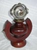
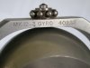
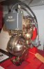
One of the reasons that I love to collect fuses is mostly due with my life long fascination of "mechanisms" - whether it is out of a clock, car, camera or some other device. Here's a beaut German WW2 T-5 (or earlier) torpedo gyro that I was fortunate to come across a few years ago. It is most likely a training one as it came complete with the stand and has most of it's bits - as others I have seen in the past are not as complete.
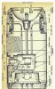
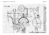
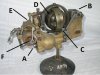
Apart from the typical German instrument precision, I found it quite fascinating how it actually operates......I have added letters to the first pic and will describe the sequence of events when the torpedo is launched and how the gyro initializes.....
Point A:
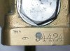
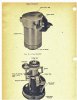
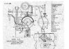
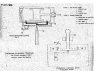
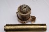
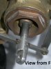
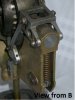
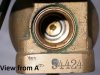
Upon launching, compressed air enters the ball shape chamber from beneath the gyro (the 2nd pic shows the view of the internal chamber when the bolt has been removed - where you can see the head of the piston). In a similar operation to that of a 1st stage Piston SCUBA regulator {the bit that attaches to the tank}, as the air pressure increases inside the chamber, the mechanical advantage (surface area of the piston head) will slowly overcome the spring tension (View from B pic) and move forwards towards the rear of the gyro.
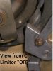
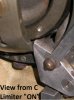
Point B & C:
The mechanical linkage shown at point B, connects to a movement limiter at point C, which restricts the gyro movement in the horizontal plane.
As the piston continues to move rearwards, the movement limiter moves up and backwards to a point where the gyro is freely to operate.
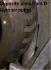
Point D:
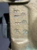
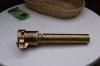
The gyro wheel has "slots" evenly cut around its circumference, which help assists the initial airflow to spin the gyro up to its operating 15,000 rpm. You can observe the gyro air outlet in the "Opposite View from D" pic.
So the movement limiter is design to keep the gyro in a restrictive position until it has reached its operational spin - this startup time has been calculated as the time it takes the air in the internal chamber to pressurized the piston and via mechanical linkage, release the movement limiter.
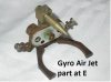
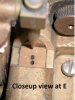
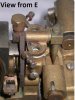
Point E:
Once operational, the gyro controls the steering (left or right) by the movement of the nozzle which injects 6 kilos pressure into a housing which in turns moves the lower piston left or right.
Point F:
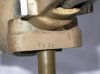
Steering piston - which is eventually linked to the torpedo's rubber.
There are also some other pre-adjustments as shown on the front above the steering piston, which I assumed to be used to pre-set the torpedo's course.
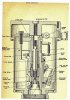
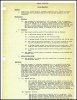
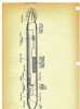
I had a rough idea how it worked when I got it (I use to service my own diving equipment) - it took another 6 mths to verify the operation when I came across some U-boat archives, specifically U-371, whose crew were captured and "quizzed" by the US Navy.
I'll post those drawings in the near future in addition to pics of the gyro's stamps and markings.
Enjoy!
Cheers
Drew
BTW - I have "spun" this sucker up - unbelieveable!!! Spins forever!
One of the reasons that I love to collect fuses is mostly due with my life long fascination of "mechanisms" - whether it is out of a clock, car, camera or some other device. Here's a beaut German WW2 T-5 (or earlier) torpedo gyro that I was fortunate to come across a few years ago. It is most likely a training one as it came complete with the stand and has most of it's bits - as others I have seen in the past are not as complete.
Apart from the typical German instrument precision, I found it quite fascinating how it actually operates......I have added letters to the first pic and will describe the sequence of events when the torpedo is launched and how the gyro initializes.....
Point A:
Upon launching, compressed air enters the ball shape chamber from beneath the gyro (the 2nd pic shows the view of the internal chamber when the bolt has been removed - where you can see the head of the piston). In a similar operation to that of a 1st stage Piston SCUBA regulator {the bit that attaches to the tank}, as the air pressure increases inside the chamber, the mechanical advantage (surface area of the piston head) will slowly overcome the spring tension (View from B pic) and move forwards towards the rear of the gyro.
Point B & C:
The mechanical linkage shown at point B, connects to a movement limiter at point C, which restricts the gyro movement in the horizontal plane.
As the piston continues to move rearwards, the movement limiter moves up and backwards to a point where the gyro is freely to operate.
Point D:
The gyro wheel has "slots" evenly cut around its circumference, which help assists the initial airflow to spin the gyro up to its operating 15,000 rpm. You can observe the gyro air outlet in the "Opposite View from D" pic.
So the movement limiter is design to keep the gyro in a restrictive position until it has reached its operational spin - this startup time has been calculated as the time it takes the air in the internal chamber to pressurized the piston and via mechanical linkage, release the movement limiter.
Point E:
Once operational, the gyro controls the steering (left or right) by the movement of the nozzle which injects 6 kilos pressure into a housing which in turns moves the lower piston left or right.
Point F:
Steering piston - which is eventually linked to the torpedo's rubber.
There are also some other pre-adjustments as shown on the front above the steering piston, which I assumed to be used to pre-set the torpedo's course.
I had a rough idea how it worked when I got it (I use to service my own diving equipment) - it took another 6 mths to verify the operation when I came across some U-boat archives, specifically U-371, whose crew were captured and "quizzed" by the US Navy.
I'll post those drawings in the near future in addition to pics of the gyro's stamps and markings.
Enjoy!
Cheers
Drew
BTW - I have "spun" this sucker up - unbelieveable!!! Spins forever!
Attachments
-
 German Gyro 10.jpg90.9 KB · Views: 52
 -
 German Gyro 1.jpg45.3 KB · Views: 116
 -
 German Gyro 9.jpg52.4 KB · Views: 56
 -
 German Gyro 8.jpg47.7 KB · Views: 55
 -
 German Gyro 7.jpg48.4 KB · Views: 65
 -
 German Gyro 6.jpg77.7 KB · Views: 60
 -
 German Gyro 5.jpg70.9 KB · Views: 61
 -
 German Gyro 4.jpg97.2 KB · Views: 64
 -
 German Gyro 3.jpg85.7 KB · Views: 74
 -
 German Gyro 2.jpg64.2 KB · Views: 82
Last edited:
")