pzgr40
Well-Known Member
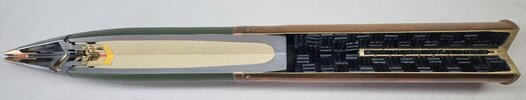
Cutaway model of an M48 high explosive shell for the M2 to M6 guns, equipped with the P.D.M48A2 fuze, SQ & 0.15 sec. delay.
The M2 to M6 guns were used in the M3 Lee tank, M4 Sherman tank, the M24 Chaffee, but was also used in the B25H Mitchel twin-engine bomber, which was used in the Pacific to hunt Japanese shipping.
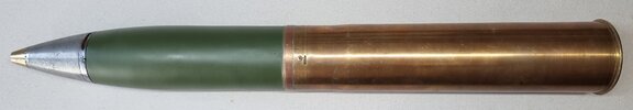
The projectile is made of mild steel and has a boat tail, which improves the range over the (older) flat base M41A1 type. The projectile body is filled with 0.67 Kg (1.49 Lb) TNT or Amatol 50/50.
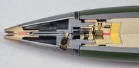
The top of the projectile body is threaded to receive the M20A1 booster. The M48A1 fuze is screwed into the M20A1 booster. The M20A1 booster is used under several American fuzes. The M20A1 booster has a brass body with an aluminium cap screwed over the bottom of the booster body, containing the main charge of 22 grams of Tetryl. In top of the booster is a brass safety rotor with a heat-sensitive detonator, locked in the transport position (turned out of the center line) by two safety pins, one of which is a vertical spring loaded inertia pin that is inserted through the -radial- spring loaded centrifugal safety pin, and fixates the centrifugal safety pin. After firing, the inertia pin swings backward and releases the centrifugal safety pin that swings outward, which releases the safety rotor, allowing it to rotate the detonator in the safety rotor into line with the explosion chain. A lead charge (red) is located between the safety rotor and the Tetryl booster.
The fuze used on this projectile is the M48A2 SQ (SuperQuick), a percussion and concussion fuze with an adjustable delay of 0.15 seconds. The delay can be set by turning the screw on the outside of the fuze body 90 degrees. In the brass nose of the fuze is a duplex detonator (orange) is placed with a fixed firing pin above it. The firing pin is kept away from the duplex detonator by a copper collar with a diameter of 5 mm and a wall thickness of 0.3 mm. On impact the firing pin is driven into the detonator -crushing the copper collar- causing the flame to travel through the steel tube and down into the safety rotor, which detonates, igniting the lead charge that ignites the booster. This part of the fuze is the percussion fuze. When the screw is set to open the channel (Superquick), the brass cylinder blocking the central channel swings outward under centrifugal force, opening the channel. It should be noted that the cylinder is set at an angle of approximately 15 degrees downward relative to the center of the fuze. This is done to ensure that the inertia force at firing is greater than the centrifugal force upon firing the shot. Therefore, the cylinder can only slide open when the acceleration is over, approximately 25 meters after leaving the barrel.
If the screw is turned 90 degrees, the cylinder cannot move outward, the channel blocks, and the delayed -concussion- fuze in the lower part of the fuze will be activated. This lower part of the fuze contains a steel bushing in which a brass inertia cylinder is placed which is held in the afterward position by a spring. Two radially mounted centrifugal safety bushings are positioned opposite each other in the inertia cylinder and these fix the inertia cylinder in the rear position because the cylinders rest against a flame guidance tube. After firing, the two cylinders that lock the inertia cylinder are thrown outwards. On impact, the brass inertia cylinder moves forward, pushing the primer of the pyrotechnic delay element into the firing pin (blue). The delay element provides a delay of 0.15 seconds before the flame travels via an angled channel into the safety rotor. This part of the igniter is the concussion igniter with built-in delay.
The 0.15 second delay of the fuze allowed the gunner to fire through a wall before the grenade detonated inside the building.
The brass case M18 is 350mm long. The M31A2 percussion cap is pressed into the base and has a magazine consisting of a brass tube with holes. The magazine is filled with coarse grained black powder that ignites the main charge of powder in the case. The case is filled with 0.52 kg of M1 powder.
There are three case charges available for this cartridge; the reduced charge containing 0.254 kg (0.56 Lbs) of FNH powder, the normal charge containing 0.512 kg (1.13 Lbs) of FNH powder and the super charge containing 0.907 kg (2 Lbs) of FNH powder. The cross section shown here uses the super charge.
The reduced charge has a black cross painted on the bottom of the shell case, two black bands under the neck of the case with the text ‘reduced’ in between, the normal charge has a single black stripe across the bottom of the shell case, a black band under the neck of the case with the text ‘normal’ underneath, the super charge only has the text ‘super’ on the bottom of the shell case and the side of the case.
An interesting detail about this shell case ; when the American troops joined the war on the Western Front in 1917, they had hardly any artillery with them. This shortage was filled by taking over M1897 guns from France. In 1918, these guns were taken to the USA. The M1897 gun was further developed as the 75mm M3 tank gun that was built into the M4 Sherman tank. And the case of the M3 gun of the….make an educated guess… dimensional identical to the shell case of the French M1897 field gun. Because the Sherman tank was intended as a support tank for the infantry, and not to fight other tanks, so a field gun as main armament was considered sufficient. That the practice of war later changed this is another story.
Length of the complete cartridge : 26,6 inch (676 mm)
Length of the projectile body : 11,22 inch (285 mm)
Cartridge weight : 18,80 Lb (8,52 kg) with super charge
Regards, DJH
The M2 to M6 guns were used in the M3 Lee tank, M4 Sherman tank, the M24 Chaffee, but was also used in the B25H Mitchel twin-engine bomber, which was used in the Pacific to hunt Japanese shipping.
The projectile is made of mild steel and has a boat tail, which improves the range over the (older) flat base M41A1 type. The projectile body is filled with 0.67 Kg (1.49 Lb) TNT or Amatol 50/50.
The top of the projectile body is threaded to receive the M20A1 booster. The M48A1 fuze is screwed into the M20A1 booster. The M20A1 booster is used under several American fuzes. The M20A1 booster has a brass body with an aluminium cap screwed over the bottom of the booster body, containing the main charge of 22 grams of Tetryl. In top of the booster is a brass safety rotor with a heat-sensitive detonator, locked in the transport position (turned out of the center line) by two safety pins, one of which is a vertical spring loaded inertia pin that is inserted through the -radial- spring loaded centrifugal safety pin, and fixates the centrifugal safety pin. After firing, the inertia pin swings backward and releases the centrifugal safety pin that swings outward, which releases the safety rotor, allowing it to rotate the detonator in the safety rotor into line with the explosion chain. A lead charge (red) is located between the safety rotor and the Tetryl booster.
The fuze used on this projectile is the M48A2 SQ (SuperQuick), a percussion and concussion fuze with an adjustable delay of 0.15 seconds. The delay can be set by turning the screw on the outside of the fuze body 90 degrees. In the brass nose of the fuze is a duplex detonator (orange) is placed with a fixed firing pin above it. The firing pin is kept away from the duplex detonator by a copper collar with a diameter of 5 mm and a wall thickness of 0.3 mm. On impact the firing pin is driven into the detonator -crushing the copper collar- causing the flame to travel through the steel tube and down into the safety rotor, which detonates, igniting the lead charge that ignites the booster. This part of the fuze is the percussion fuze. When the screw is set to open the channel (Superquick), the brass cylinder blocking the central channel swings outward under centrifugal force, opening the channel. It should be noted that the cylinder is set at an angle of approximately 15 degrees downward relative to the center of the fuze. This is done to ensure that the inertia force at firing is greater than the centrifugal force upon firing the shot. Therefore, the cylinder can only slide open when the acceleration is over, approximately 25 meters after leaving the barrel.
If the screw is turned 90 degrees, the cylinder cannot move outward, the channel blocks, and the delayed -concussion- fuze in the lower part of the fuze will be activated. This lower part of the fuze contains a steel bushing in which a brass inertia cylinder is placed which is held in the afterward position by a spring. Two radially mounted centrifugal safety bushings are positioned opposite each other in the inertia cylinder and these fix the inertia cylinder in the rear position because the cylinders rest against a flame guidance tube. After firing, the two cylinders that lock the inertia cylinder are thrown outwards. On impact, the brass inertia cylinder moves forward, pushing the primer of the pyrotechnic delay element into the firing pin (blue). The delay element provides a delay of 0.15 seconds before the flame travels via an angled channel into the safety rotor. This part of the igniter is the concussion igniter with built-in delay.
The 0.15 second delay of the fuze allowed the gunner to fire through a wall before the grenade detonated inside the building.
The brass case M18 is 350mm long. The M31A2 percussion cap is pressed into the base and has a magazine consisting of a brass tube with holes. The magazine is filled with coarse grained black powder that ignites the main charge of powder in the case. The case is filled with 0.52 kg of M1 powder.
There are three case charges available for this cartridge; the reduced charge containing 0.254 kg (0.56 Lbs) of FNH powder, the normal charge containing 0.512 kg (1.13 Lbs) of FNH powder and the super charge containing 0.907 kg (2 Lbs) of FNH powder. The cross section shown here uses the super charge.
The reduced charge has a black cross painted on the bottom of the shell case, two black bands under the neck of the case with the text ‘reduced’ in between, the normal charge has a single black stripe across the bottom of the shell case, a black band under the neck of the case with the text ‘normal’ underneath, the super charge only has the text ‘super’ on the bottom of the shell case and the side of the case.
An interesting detail about this shell case ; when the American troops joined the war on the Western Front in 1917, they had hardly any artillery with them. This shortage was filled by taking over M1897 guns from France. In 1918, these guns were taken to the USA. The M1897 gun was further developed as the 75mm M3 tank gun that was built into the M4 Sherman tank. And the case of the M3 gun of the….make an educated guess… dimensional identical to the shell case of the French M1897 field gun. Because the Sherman tank was intended as a support tank for the infantry, and not to fight other tanks, so a field gun as main armament was considered sufficient. That the practice of war later changed this is another story.
Length of the complete cartridge : 26,6 inch (676 mm)
Length of the projectile body : 11,22 inch (285 mm)
Cartridge weight : 18,80 Lb (8,52 kg) with super charge
Regards, DJH