
pzgr40
Well-Known Member
The 67 mm Armbrust (Crossbow) is a single use, expandable weapon, and cannot be reused. The Armbrust is factory loaded with a HEAT projectile, an inert practice version of the HEAT projectile, either a HE-FRAG projectile. The Armbrust was developed by the German Messerschmidt Bolkow-Blom Gmbh company (MBB for short), subsequently DASA. Production of the Armbrust seized in 1988, when it was replaced by the Matador around the year 2000. The Belgian PRB company produced the Armbrust in licence. The rights to produce the Armbrust were finally sold to the SIngaporese firm CAI (Chartered Ammunition Industries) which continued to offer the Armbrust. The Armbrust is mentioned in the Jane’s infantry weapons of 1976, so I presume the design must be around the 1970’s.
Complete length of the Armbrust is 850 mm.
The Armbrust is an unique weapon as;
-It uses the davies countermass principle (weight projected forward = weight projected backward).
-It produces no flash upon firing.
-It produces no smoke upon firing.
-The sound upon firing is not louder than a .22Lr.
-It can be fired from encloced spaces where the distance between the back of the barrel and a wall is just one meter (3 Ft)
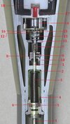
The barrel consits of a high tensile strength steel pipe in which two opposing aluminum pistons are placed (picture 05), connected by a threaded rod which protrudes forward from the aft piston. This rod has a weakening in the middle that acts as a breaking point. Around the threaded rod a bushing with two white plastic caps is placed containing the ignition charge which ignites the main propelling charge of powder, placed between the two pistons and around the ignition charge. The ignition charge is started by a piezo electric igniter (picture 04), placed in the handgrip of the Armbrust.
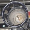
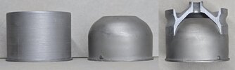
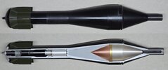
In the front a factory loaded HEAT or HE-FRAG projectile is placed before the forward piston, screwed into the connection rod oft he afterward piston by means of a small threaded breaking rod at the back end of the projectile (Picture 10 and 11) to enshure the projectile will not fall out of the weapon. Behind the rear piston the countermass is placed (picture06), consisting of four stacks (picture 08) of appr 1250 plastic flakes (picture 05) each, which have the same weight as the projectile in the front. Each stack is tied together with a thin rope. These ropes are connected to a small eye at the rear of the afterward piston to enshure the stacks stay in shape. Four T-shaped plastic filler pieces run along the length of the stacks, enshuring an even distribution of stacks inside the pipe, and guidance when ejected. A circular array of triangular plastic shims (picture 08) is placed in the afterward piston, forming a flat surface upon which the four stacks of plastic flakes are supported. In both the forward and rear end of the pipe a flanged bushing (picture 09) is placed which forms the shock absorber and brake for the pistons when the armbrust is fired.The front end has a threaded ring which is screwed over the front end of the pipe to lock up the forward shock absorber. It has a crown shaped sheet metal ring crimped in place to protect the nose piece of the projectile protruding from the front end of the pipe. At the back end of the pipe a threaded ring screwed to lock up the afterward shock absorber. A rubber cover is placed over the afterward threaded ring to keep the inner works of the armbrust moist free.
The handgrip of the Armbrust is made from black plastic and contains the piezo electric fuze with the trigger to ignite the propelling charge, the fold out shoulder support, and the fold out hand grip. When folded in, the hand grip forms the cover and safety for the trigger. On the side of the pipe, a polyurethane cushion is placed (picture 01), housing the reflex sight. The reflex sight is protected by a rip away cover that keeps the sight moist free.
Before firing, the rip away cover is removed, the sight is rotated in line. The hand grip and the shoulder support are folded out. The Armbrust is placed on the right shoulder and the Armbrust is aimed at the targert. When the trigger is pulled, a spark ignites the ignition charge, which ignites the main propelling charge. The two pistons are pushed away from one another with 420mtrs/ sec, to the front throwing away the projectile, to the back pushing out the stacks of plastic flakes which break the rubber cover and are thrown outward. The two pistons will engage the rims of the shock absorber pipes and ‚scoop‘ the pipes simultaniously, pressing the straight pipe pieces into rounded cups (picture 09). This deformation has two purposes; slowing down the pistons when reaching the end of path, and forming a gastight seal so no gas can escape.
At the front end the small connection rod between the piston and the projectile breaks and the projectile is thrown away with 210 mtrs/sec (690 ft/sec), at the back the stacks of flakes are thrown out with the same speed. However these stacks fall apart and due to the light weight of the seperate flakes they lose momentum rapidly, forming a cloud of ‚confetti‘ behind the armbrust. This allows the Armbrust to be fired from an enclosed space with only one meter between the afterward end oft he Armbrust and a wall, without any risc for the soldier. As both pistons are caught by the flanged pipes and no gas escapes, no flash and no smoke will be visable , and the sound produced is by the pistons hitting and deforming the two pipe pieces. It is stated that this is not louder than the sound of a .22 Lr being fired.
After firing, the armbrust must be thrown of the shoulder immediately, as the pipe is very hot. Hence the handgrip and the cushion, so no body parts are in direct contact with the pipe.
An advantage of the Armbrust was that is was very suitable for combat in urban settings, as the soldier firing it is left nearly undetected.
The disadvantage of the armbrust is that it can only be used once, has a relatively low effective firing range of 300 meters, and a relatively low penetration of 300 mm steel. Therefore, -even when designed- it was suitable to combat armoured vehicles and light tanks (from the side and the back), but not main battle tanks. The appearance of (re)active armour made the Armbrust obsolete.
The HE-FRAG version of the Armbrust suffered from the same disadvantages, although silent and difficult to spot the firing point, modern HE-FRAG automatic grenade launchers and underslung grenade throwers have the same result without having to carry a heavy single shot disposable weapon into the battlefield.
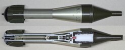
The HEAT projectile (pictures 02 and 10)
It has a main charge 170 grams of RDX 95/5, the copper cone 55 weighs grams, complete weight of the projectile is 980 grams.
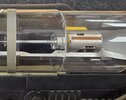
Arming of the projectile is generally the same as the HE-FRAG projectile as far as the breaking rod with pin, allowing the fuze to arm only after being releasesd from the forward piston. Regretfully only a dummy fuze is placed in this practice version of the HEAT projectile. A picture of the fuze is taken from a perspex factory model of the Armbrust (picture 14).
The fuze is armed 6-12 meters after being fired. No further info about the fuze is available, but I suspect it is also a set back mechanical impact fuze.
Countries that have used the Armbrust:
Brunei, Cambodia, Chile, Kosovo, Yugoslavia (former), Singapore, Germany, Indonesia, Philippines. With most countries by special forces.
Regards, DJH.
Attachments
-
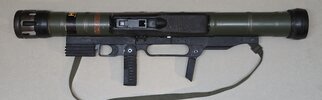 01 - MBB Armbrust sideview.jpg612.8 KB · Views: 19
-
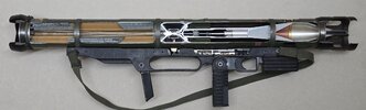 02 - MBB Armbrust with HEAT projectile.jpg4 MB · Views: 15
-
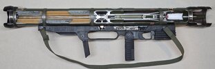 03 - MBB Armbrust with HE-FRAG projectile.jpg649 KB · Views: 15
-
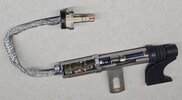 04 - Piezo electrisc gnition mechanism.jpg1.3 MB · Views: 15
-
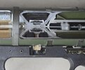 05 - MBB Armbrust combustion chamber and pistons.jpg1.1 MB · Views: 13
-
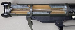 06 - MBB Armbrust countermass.jpg1.1 MB · Views: 12
-
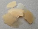 07 - MBB Armbrust countermass flakes .jpg1.2 MB · Views: 9
-
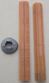 08 - MBB Armbrust sticks of countermass flakes and support shims ring.jpg1.5 MB · Views: 11
-
 09 - Shock absorber and brake pipe before and after deformation.jpg1.4 MB · Views: 13
-
 10 - MBB Armbrust HEAT projectile.jpg1.1 MB · Views: 19