pzgr40
Well-Known Member
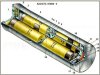
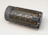
Cutaway model of a Pom-2s mine. This Russian scatterable anti-personnel fragmentation mine is a hand- dispenser- or missile-deployed self-righting mine with a self-destruct mechanism. An interesting mine because it is currently being used in the Ukraine (Picture 01).
The mine is intended to quickly create a temporary -nearby of far away- minefield that clears itself after a minimum of four and a maximum of hundred hours.
This cutaway model was not made by me, but by Joop Dijkman from the MTM museum in Landhorst, Netherlands, which is clearly visible by the unsurpassed high quality.
I made the attached drawings in autocad on the basis of Russian drawings and measurements, this because the drawings in the Russian manuals were a copy of a copy which had become blotchy and unclear and were not always completely correct.
The PDF (photo 20) shows the operating sequence of the VP-09S fuze, numbered 1 to 5. The parts drawn in purple are the parts that are currently moving/working, the red arrow shows the direction of the movement of the part or group of parts.
It may be helpful to print the text with the VP-09S igniter (Picture 19), as it will be easier to read if you don't have to scroll up and down.
The mine can be laid in a number of different ways; by hand (Pom-2P), using a KPOM-2 cassette in a dispenser system (PKM, VSM-1, UMZ), using 122mm Grad or 300mm Smerch artillery missiles, and through field modifications as encountered in Ukraine where the mine is fired and laid at close range by means of an RPG-7. There are even reports that the mine is being laid by mortars and drones.
https://www.youtube.com/watch?v=CmmeF7lKQaQ
0:00 - 00:35 PKM,
00:37 – 1:26 UMZ
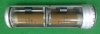
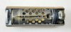
Picture 02 - The KPOM-2 cassette contains four mines that are packed airtight. The cassette is an aluminum tube 480mm long and 140mm in diameter with an electric detonator ampoule on one side, and a lid on the other side, between which the four Pom-2S mines are placed in two pairs. When the electric detonator is ignited, the expulsion charge is ignited as well the fuses of the four mines, and the mines are ejected. Between two adjacent mines a strong leaf spring is placed that pushes the mines apart. Because the rear two mines have more 'barrel length' when ejected from the cartridge, they are thrown further away.
Picture 03 - The PKM dispenser is the simplest version to activate a KPOM-2 cassette. The PKM consists of a base plate on which a rimmed flange in which a KPOM-2 cassette fits. The flange is placed at a fixed angle of 45 degrees. The KPOM-2 cassette is ignited by an electrical pulse and then disperses the mines. The advantage of the PKM is that it can be placed far in advance to quickly lay a minefield at any desired moment. The mines are shot away between 30 and 35 meters.
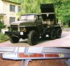
Picture 04 – In the VSM-1 dispenser version, as used in helicopters (Mi-8 MT), 116 KPOM-2 cassettes are placed pointing vertically downwards in the dispenser. Four mines are ejected downwards from each cassettes. In total, the system contains 464 Pom-2S mines. These cassettes are activated at regular intervals during flight, enabling the creation of a 2300m long minefield with the helicopter flying at speeds of up to 220km/h at an altitude of between 30-100m.
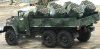
Picture 05 - Six dispensers are placed on a truck at the UMZ minelayer. Each dispenser has 30 slots housing a KPOM-2 cassette containing 4 POM-2S mines, so 120 mines per dispenser. The mines are launched from the KPOM-2 cassettes into the air. 6 dispensers are placed on a truck, so a total of 720 mines can be laid between 40 and 110 meters from the vehicle while driving. As the dispensers can be rotated, the density and width of the minefield can be adjusted.
Picture 05 - Six dispensers are placed on a truck at the UMZ minelayer. Each dispenser has 30 slots housing a KPOM-2 cassette containing 4 POM-2S mines, so 120 mines per dispenser. The cassettes are launched from the vehicle after which the mines are ejected mid the air from the cassette. 6 dispensers are placed on a truck, so a total of 720 mines can be laid between 40 and 110 meters from the vehicle while driving. As the dispensers can be rotated, the density and width of the minefield can be adjusted.
Picture 06 - The 122mm 9K22M1 missile is fired from the BM-21 Grad (Hail). The warhead placed on the missile contains 5 Pom-2S mines. Forty missiles can be fired in a salvo, laying 200 mines at a distance of between 1.5 and 13.4 km.
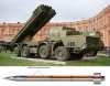
Picture 07 - The BM-30 Smerch (Tornado) fires the 300mm 9M55K3 missile in which houses 64 Pom-2S mines.
The BM30 has 10 launching pipes, so a BM-30 can lay a minefield of 640 mines at a distance between 20 and 120 kilometers
Here's a movie with the rocket in action; https://www.youtube.com/watch?v=fYnBmxjfld4 between 3:28 and 3:42 the mine can be seen in action.
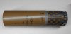
Picture 08 - A hand placed version of the Pom-2 is also available; the Pom-2P and the Pom2P1, these are intended for Spetznaz (reconnaissance/commando troops) as a pursuit discouragement mine. Both have a self-destructor that destroys the mine between 40 and 100 hours. The difference between the Pom-2P and the Pom-2P1 is the arming time, 120 seconds and 50 seconds respectively.
There are also versions without a self-destruction mechanism; the Pom-2RBS, which arms after 120 seconds, and the Pom-2R1BS, which arms after 50 seconds.
However, these four versions differ from the version fired by artillery or dispenser.
POM-2 mine in operation...https://youtu.be/1hw8xblFbew
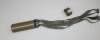
Picture 09 - A field modified version is the POM-2 RPG. This was found in eastern Ukraine, and is intended to place the Pom-2 at a short distance - the next trench - in enemy territory.
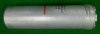
Picture 10 - The complete Pom-2S mine as packed in the PKM, UMZ, KPOM-2 or missile. On the left one can see the hole in the base of the tubular casing through which the pyrotechnic fuse is ignited during the ejection from the KPOM-2 canister or from the rocket body
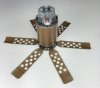
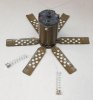
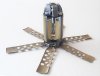
Picture 11 & 12 – Cutaway model of a complete Pom-2S mine in cross section (picture 11) and of the tubular casing only (picture 12). On picture 11 and 12 from left to right; the disc with the circular pyrotechnic fuse that burns for 54 seconds, the ignition charge (red) for the black powder charge above it, the steel cap that fixates the six spring-loaded footplates in the inner position, the mine itself, the flange which houses the cloth ribbons and central shaft with the pressure spring, and the closing cap.
The split pin through the hole in central shaft fixating the closing cap (right picture 12) is only there for factory transport, when the mine is placed in the KPOM-2 cassette or in the missile it is removed.
Picture 13 - The mine after it has been ejected from the KPOM-2 cassette or missile, and is suspended mid-air. The pressure spring pushes the closing cap off, the ribbons unroll and provide the orientation of the mine. The circular pyrotechnic 54 seconds fuse in the disc still burns.
Picture 14 - The mine in the tubular casing lands on the ground. The 54 seconds pyrotechnic fuse in the disc continues to burn until it ignites the black powder charge which in turn ignites the pyrotechnic fuse (01) in top of the mine's VP-09S fuze (Picture -19) and expulses the mine (with the cap housing the six spring-loaded footplates in the inner position still kept in place) and the cap with the ribbons from the tubular casing. The photo shows the moment the moment of expulsion.
Picture 15 – The mine as it lays on the ground after being ejected from the tubular casing.
Picture 16 – The upper pyrotechnic fuse of the VP-09S fuze burns for 3,5 seconds, after which the fuze ejects the upper pyrotechnic fuse housing with the double fork, taking with it the cap that keeps the six spring loaded foot plates fixated inward. The top of the fuze is now unlocked as both shafts (7) have moved inwards. The mine rotates in the upright position. The upper pyrotechnic fuze has lit the lower pyrotechnic fuze in the mine’s fuze body .
Picture 17 - When the lower pyrotechnic fuse has burned out, the top of the fuze is blown off and the tripwires are ejected. The VP-09S fuze is now fully armed, and the self-destruct mechanism timer is activated.
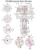
Operation of the VP-09S fuze (drawings / pictures 19 and 20):
When the mine has been ejected from the cap (see pict. 15) that fixates the six spring-loaded foot plates against the mine body and has subsequently set itself upright, the pyrotechnic fuze (01) simultaneously burns up in 3.5 seconds so that the pyrotechnic fuze housing (02) is blown out of it’s outer housing (04) by the black powder charge (03). The pyrotechnic fuze housing (02) is fixated in the outer housing (04) by means of a folded edge in top which is bend open. It also has an U shaped fork (05) swaged in top facing downward, the ends of which are placed over two springloaded (06) shafts (07). The two spring-shaft combinations are placed directly opposite one another, although only one can be seen in this cross-section (drawing 19) because the cutaway of the drawing is not a 180-degree cut out, but 135 degrees to show the most important parts in one single drawing.
When the pyrotechnic fuze housing (02) is blown away upward with the fork (05), the shafts (07) can move inwards and the top part (08) of the fuze is unlocked relative to the lower part (09) of the fuze. The top part (8) is now connected only to the lower part (09) of the fuze by means of two screws with a shear groove (10 Section A-A). The pyrotechnic fuze (11) in the fuze housing (12) burns up, after which the ejector charge (13) blows the complete top part (08) of the fuze away from the lower part (9), breaking the two screws (10) over the break groove. The steel plate (14) that protects the rubber cover (15) is also blown away and allows the rubber cover underneath to rise.
The purpose of blowing away the top part of the fuze (08) is to release the four spring-loaded (16) wire spools (17), each containing 10 meters of thin wire (18), ensuring the spools are ejected with speed and the wires are placed at a 90 degrees angle from each other. The spool with the spring attached forms the end of the wire and hooks behind vegetation to keep the wire taut.
As long as the top of the fuze (08) is still fixated to the lower part (09) by the two screws (10), the firing pin housing (19) is forced down by the disc (14). This forces the lower part of the firing pin housing (19) over the arming slider (20) fixating it, keeping the firing pin (21) out of line with the detonator (22).
Under the influence of the pressure spring (23) the housing of the self-destruct mechanism (24) moves upwards together with the firing pin housing (19), releasing the arming slider (20) and allowing it to move into the armed position by its spring (25). The same movement also takes place at the top, where the rotor (26) is pushed upward so far that it is above the green line and can now rotate freely. The green line forms a step where the rotor -when the mine is in the safe position- is fixed in the lower position and cannot rotate, but it can rotate freely in the upper position. The assembly of the following parts moves upwards: 19,21,24, 27,30,31,32,33,34,35,36. The spring (23) moves the assembly.
With the rotor and firing pin assembly risen to armed condition, the two balls (27) fall in the groove outlined in blue. In section B-B it can be seen that the balls fixate the firing pin (21) when they are in the R-R line in the arming sleeve (37). In section B-B it can also be seen that if the assembly is rotated by turning the rotor (26) clockwise, the balls also rotate clockwise and fall into the wider part (28), allowing the balls to move outward, releasing the firing pin, detonating the mine. In section A-A a top view of the rotor (26) can be seen, with the tripwires shown in red which pass through the rotor and exit through two holes in the lower part of the tube (9). Two wires are joint together by means of a bead (38) just outside the lower fuze housing (09) into a Y shape to form a single wire that is attached to the rotor in the lower fuze housing. The mine is activated by a pull on one of the four tripwires with just 0.3 kg.
Self-destruction takes place between four and hundred hours. The self-destruct mechanism consists of a cylinder (24), in which a piston (30) with a sliding fit is placed, pressed upwards by a spring (31). The piston is rigidly connected to two shafts (32 & 33); the lower shaft (32) over which the firing pin housing (19) has been screwed at the lower end, and the upper shaft (33) which is intended to keep the firing pin housing (19) in the lower position in safe condition when the upper fuze housing (08) is still in place. The base of the piston (30) is closed by a disc (34). Both spaces above and below the piston (35) are filled with grease. In the piston (30) is a small hole is drilled (36). The spring (31) pushes the piston slowly upwards, slowly pushing the grease through the hole (36) from the upper chamber into the lower chamber. When the piston is in the upper position, the two steel balls (27) are still in the R-R line of section B-B, but above the blue Z-Z line. They therefore can move outward in the wider area of the arming sleeve (37), releasing the firing pin, detonating the mine.
Self-destruction takes place between 4 and 100 hours; If the mine is placed in the desert of Iraq it will become very hot, and the fat in the self-destruct mechanism becomes less viscous causing the mine to detonate after four hours. If the same mine is used in the polar circle in winter conditions the viscosity of the fat will be very high and self-destruct will occur after 100 hours only.
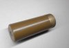
The tubular casing (with cap as in picture 10) is 177 mm long and has a diameter of 62.7 mm
The mine itself (picture 16) with fuze is 122 mm high, when armed (picture 17) 96 mm high, and has a body diameter of 57.5 mm
The diameter of the unfolded footplates is 272mm
The mine weighs 1.6 kg and has a bursting charge of 140 grams of TNT.
The fragmentation of the mine is fatal to at least 16 meters radius and will injure persons up to 50 meters radius.
Once laid, the mine cannot be manually disarmed or neutralized. If neutralization is required this is done from a distance by means of rifle fire.
The mine cannot be neutralized by manually placing an explosive charge beside the mine because one never knows how far the self-destruct mechanism has expired to the mine's point of detonation.
The Pom-2S has been used in Afghanistan and Chechnya and is currently used in Ukraine. Possibly Syria too.
Regards, DJH
The mine is intended to quickly create a temporary -nearby of far away- minefield that clears itself after a minimum of four and a maximum of hundred hours.
This cutaway model was not made by me, but by Joop Dijkman from the MTM museum in Landhorst, Netherlands, which is clearly visible by the unsurpassed high quality.
I made the attached drawings in autocad on the basis of Russian drawings and measurements, this because the drawings in the Russian manuals were a copy of a copy which had become blotchy and unclear and were not always completely correct.
The PDF (photo 20) shows the operating sequence of the VP-09S fuze, numbered 1 to 5. The parts drawn in purple are the parts that are currently moving/working, the red arrow shows the direction of the movement of the part or group of parts.
It may be helpful to print the text with the VP-09S igniter (Picture 19), as it will be easier to read if you don't have to scroll up and down.
The mine can be laid in a number of different ways; by hand (Pom-2P), using a KPOM-2 cassette in a dispenser system (PKM, VSM-1, UMZ), using 122mm Grad or 300mm Smerch artillery missiles, and through field modifications as encountered in Ukraine where the mine is fired and laid at close range by means of an RPG-7. There are even reports that the mine is being laid by mortars and drones.
https://www.youtube.com/watch?v=CmmeF7lKQaQ
0:00 - 00:35 PKM,
00:37 – 1:26 UMZ
Picture 02 - The KPOM-2 cassette contains four mines that are packed airtight. The cassette is an aluminum tube 480mm long and 140mm in diameter with an electric detonator ampoule on one side, and a lid on the other side, between which the four Pom-2S mines are placed in two pairs. When the electric detonator is ignited, the expulsion charge is ignited as well the fuses of the four mines, and the mines are ejected. Between two adjacent mines a strong leaf spring is placed that pushes the mines apart. Because the rear two mines have more 'barrel length' when ejected from the cartridge, they are thrown further away.
Picture 03 - The PKM dispenser is the simplest version to activate a KPOM-2 cassette. The PKM consists of a base plate on which a rimmed flange in which a KPOM-2 cassette fits. The flange is placed at a fixed angle of 45 degrees. The KPOM-2 cassette is ignited by an electrical pulse and then disperses the mines. The advantage of the PKM is that it can be placed far in advance to quickly lay a minefield at any desired moment. The mines are shot away between 30 and 35 meters.
Picture 04 – In the VSM-1 dispenser version, as used in helicopters (Mi-8 MT), 116 KPOM-2 cassettes are placed pointing vertically downwards in the dispenser. Four mines are ejected downwards from each cassettes. In total, the system contains 464 Pom-2S mines. These cassettes are activated at regular intervals during flight, enabling the creation of a 2300m long minefield with the helicopter flying at speeds of up to 220km/h at an altitude of between 30-100m.
Picture 05 - Six dispensers are placed on a truck at the UMZ minelayer. Each dispenser has 30 slots housing a KPOM-2 cassette containing 4 POM-2S mines, so 120 mines per dispenser. The mines are launched from the KPOM-2 cassettes into the air. 6 dispensers are placed on a truck, so a total of 720 mines can be laid between 40 and 110 meters from the vehicle while driving. As the dispensers can be rotated, the density and width of the minefield can be adjusted.
Picture 05 - Six dispensers are placed on a truck at the UMZ minelayer. Each dispenser has 30 slots housing a KPOM-2 cassette containing 4 POM-2S mines, so 120 mines per dispenser. The cassettes are launched from the vehicle after which the mines are ejected mid the air from the cassette. 6 dispensers are placed on a truck, so a total of 720 mines can be laid between 40 and 110 meters from the vehicle while driving. As the dispensers can be rotated, the density and width of the minefield can be adjusted.
Picture 06 - The 122mm 9K22M1 missile is fired from the BM-21 Grad (Hail). The warhead placed on the missile contains 5 Pom-2S mines. Forty missiles can be fired in a salvo, laying 200 mines at a distance of between 1.5 and 13.4 km.
Picture 07 - The BM-30 Smerch (Tornado) fires the 300mm 9M55K3 missile in which houses 64 Pom-2S mines.
The BM30 has 10 launching pipes, so a BM-30 can lay a minefield of 640 mines at a distance between 20 and 120 kilometers
Here's a movie with the rocket in action; https://www.youtube.com/watch?v=fYnBmxjfld4 between 3:28 and 3:42 the mine can be seen in action.
Picture 08 - A hand placed version of the Pom-2 is also available; the Pom-2P and the Pom2P1, these are intended for Spetznaz (reconnaissance/commando troops) as a pursuit discouragement mine. Both have a self-destructor that destroys the mine between 40 and 100 hours. The difference between the Pom-2P and the Pom-2P1 is the arming time, 120 seconds and 50 seconds respectively.
There are also versions without a self-destruction mechanism; the Pom-2RBS, which arms after 120 seconds, and the Pom-2R1BS, which arms after 50 seconds.
However, these four versions differ from the version fired by artillery or dispenser.
POM-2 mine in operation...https://youtu.be/1hw8xblFbew
Picture 09 - A field modified version is the POM-2 RPG. This was found in eastern Ukraine, and is intended to place the Pom-2 at a short distance - the next trench - in enemy territory.
Picture 10 - The complete Pom-2S mine as packed in the PKM, UMZ, KPOM-2 or missile. On the left one can see the hole in the base of the tubular casing through which the pyrotechnic fuse is ignited during the ejection from the KPOM-2 canister or from the rocket body
Picture 11 & 12 – Cutaway model of a complete Pom-2S mine in cross section (picture 11) and of the tubular casing only (picture 12). On picture 11 and 12 from left to right; the disc with the circular pyrotechnic fuse that burns for 54 seconds, the ignition charge (red) for the black powder charge above it, the steel cap that fixates the six spring-loaded footplates in the inner position, the mine itself, the flange which houses the cloth ribbons and central shaft with the pressure spring, and the closing cap.
The split pin through the hole in central shaft fixating the closing cap (right picture 12) is only there for factory transport, when the mine is placed in the KPOM-2 cassette or in the missile it is removed.
Picture 13 - The mine after it has been ejected from the KPOM-2 cassette or missile, and is suspended mid-air. The pressure spring pushes the closing cap off, the ribbons unroll and provide the orientation of the mine. The circular pyrotechnic 54 seconds fuse in the disc still burns.
Picture 14 - The mine in the tubular casing lands on the ground. The 54 seconds pyrotechnic fuse in the disc continues to burn until it ignites the black powder charge which in turn ignites the pyrotechnic fuse (01) in top of the mine's VP-09S fuze (Picture -19) and expulses the mine (with the cap housing the six spring-loaded footplates in the inner position still kept in place) and the cap with the ribbons from the tubular casing. The photo shows the moment the moment of expulsion.
Picture 15 – The mine as it lays on the ground after being ejected from the tubular casing.
Picture 16 – The upper pyrotechnic fuse of the VP-09S fuze burns for 3,5 seconds, after which the fuze ejects the upper pyrotechnic fuse housing with the double fork, taking with it the cap that keeps the six spring loaded foot plates fixated inward. The top of the fuze is now unlocked as both shafts (7) have moved inwards. The mine rotates in the upright position. The upper pyrotechnic fuze has lit the lower pyrotechnic fuze in the mine’s fuze body .
Picture 17 - When the lower pyrotechnic fuse has burned out, the top of the fuze is blown off and the tripwires are ejected. The VP-09S fuze is now fully armed, and the self-destruct mechanism timer is activated.
Operation of the VP-09S fuze (drawings / pictures 19 and 20):
When the mine has been ejected from the cap (see pict. 15) that fixates the six spring-loaded foot plates against the mine body and has subsequently set itself upright, the pyrotechnic fuze (01) simultaneously burns up in 3.5 seconds so that the pyrotechnic fuze housing (02) is blown out of it’s outer housing (04) by the black powder charge (03). The pyrotechnic fuze housing (02) is fixated in the outer housing (04) by means of a folded edge in top which is bend open. It also has an U shaped fork (05) swaged in top facing downward, the ends of which are placed over two springloaded (06) shafts (07). The two spring-shaft combinations are placed directly opposite one another, although only one can be seen in this cross-section (drawing 19) because the cutaway of the drawing is not a 180-degree cut out, but 135 degrees to show the most important parts in one single drawing.
When the pyrotechnic fuze housing (02) is blown away upward with the fork (05), the shafts (07) can move inwards and the top part (08) of the fuze is unlocked relative to the lower part (09) of the fuze. The top part (8) is now connected only to the lower part (09) of the fuze by means of two screws with a shear groove (10 Section A-A). The pyrotechnic fuze (11) in the fuze housing (12) burns up, after which the ejector charge (13) blows the complete top part (08) of the fuze away from the lower part (9), breaking the two screws (10) over the break groove. The steel plate (14) that protects the rubber cover (15) is also blown away and allows the rubber cover underneath to rise.
The purpose of blowing away the top part of the fuze (08) is to release the four spring-loaded (16) wire spools (17), each containing 10 meters of thin wire (18), ensuring the spools are ejected with speed and the wires are placed at a 90 degrees angle from each other. The spool with the spring attached forms the end of the wire and hooks behind vegetation to keep the wire taut.
As long as the top of the fuze (08) is still fixated to the lower part (09) by the two screws (10), the firing pin housing (19) is forced down by the disc (14). This forces the lower part of the firing pin housing (19) over the arming slider (20) fixating it, keeping the firing pin (21) out of line with the detonator (22).
Under the influence of the pressure spring (23) the housing of the self-destruct mechanism (24) moves upwards together with the firing pin housing (19), releasing the arming slider (20) and allowing it to move into the armed position by its spring (25). The same movement also takes place at the top, where the rotor (26) is pushed upward so far that it is above the green line and can now rotate freely. The green line forms a step where the rotor -when the mine is in the safe position- is fixed in the lower position and cannot rotate, but it can rotate freely in the upper position. The assembly of the following parts moves upwards: 19,21,24, 27,30,31,32,33,34,35,36. The spring (23) moves the assembly.
With the rotor and firing pin assembly risen to armed condition, the two balls (27) fall in the groove outlined in blue. In section B-B it can be seen that the balls fixate the firing pin (21) when they are in the R-R line in the arming sleeve (37). In section B-B it can also be seen that if the assembly is rotated by turning the rotor (26) clockwise, the balls also rotate clockwise and fall into the wider part (28), allowing the balls to move outward, releasing the firing pin, detonating the mine. In section A-A a top view of the rotor (26) can be seen, with the tripwires shown in red which pass through the rotor and exit through two holes in the lower part of the tube (9). Two wires are joint together by means of a bead (38) just outside the lower fuze housing (09) into a Y shape to form a single wire that is attached to the rotor in the lower fuze housing. The mine is activated by a pull on one of the four tripwires with just 0.3 kg.
Self-destruction takes place between four and hundred hours. The self-destruct mechanism consists of a cylinder (24), in which a piston (30) with a sliding fit is placed, pressed upwards by a spring (31). The piston is rigidly connected to two shafts (32 & 33); the lower shaft (32) over which the firing pin housing (19) has been screwed at the lower end, and the upper shaft (33) which is intended to keep the firing pin housing (19) in the lower position in safe condition when the upper fuze housing (08) is still in place. The base of the piston (30) is closed by a disc (34). Both spaces above and below the piston (35) are filled with grease. In the piston (30) is a small hole is drilled (36). The spring (31) pushes the piston slowly upwards, slowly pushing the grease through the hole (36) from the upper chamber into the lower chamber. When the piston is in the upper position, the two steel balls (27) are still in the R-R line of section B-B, but above the blue Z-Z line. They therefore can move outward in the wider area of the arming sleeve (37), releasing the firing pin, detonating the mine.
Self-destruction takes place between 4 and 100 hours; If the mine is placed in the desert of Iraq it will become very hot, and the fat in the self-destruct mechanism becomes less viscous causing the mine to detonate after four hours. If the same mine is used in the polar circle in winter conditions the viscosity of the fat will be very high and self-destruct will occur after 100 hours only.
The tubular casing (with cap as in picture 10) is 177 mm long and has a diameter of 62.7 mm
The mine itself (picture 16) with fuze is 122 mm high, when armed (picture 17) 96 mm high, and has a body diameter of 57.5 mm
The diameter of the unfolded footplates is 272mm
The mine weighs 1.6 kg and has a bursting charge of 140 grams of TNT.
The fragmentation of the mine is fatal to at least 16 meters radius and will injure persons up to 50 meters radius.
Once laid, the mine cannot be manually disarmed or neutralized. If neutralization is required this is done from a distance by means of rifle fire.
The mine cannot be neutralized by manually placing an explosive charge beside the mine because one never knows how far the self-destruct mechanism has expired to the mine's point of detonation.
The Pom-2S has been used in Afghanistan and Chechnya and is currently used in Ukraine. Possibly Syria too.
Regards, DJH
Attachments
-
 01 - Pom-2 in field Ukraiune.jpg167.1 KB · Views: 118
 -
 02 - KPOM-2.jpg105.6 KB · Views: 113
 -
 02A - KPOM 2.jpg305.3 KB · Views: 106
 -
 02B - KPOM-2.jpg304.9 KB · Views: 97
 -
 03 - pkm.jpg7.6 KB · Views: 94
 -
 04 - VSM-1 mining system under MI-8 MT.jpg48.5 KB · Views: 96
 -
 05 - umz-1 minelayer.jpg31.4 KB · Views: 93
 -
 06 - 9K22M1 rocket for 122mm BM-21 Grad.jpg200.8 KB · Views: 90
 -
 07 - 300mm 9M55K3 rocket for BM-30 Smerch.jpg207.2 KB · Views: 92
 -
 08 - POM-2P(1).jpg50.4 KB · Views: 94
 -
 09 - POM2RPG.png147 KB · Views: 103
 -
 10- POM2-S packed as in rocket.jpg271.9 KB · Views: 91
 -
 11 - P0M-2S in tubular casing cutaway.jpg307.1 KB · Views: 98
 -
 13 - Ejected from carrier and in flight.jpg260.1 KB · Views: 94
 -
 14 - Tubular casing ejection after landing.jpg300.1 KB · Views: 93
 -
 15 - Mine ejected.jpg262.6 KB · Views: 98
 -
 16 - Rotated in upright position.jpg262.4 KB · Views: 128
 -
 17 - armed.jpg274.3 KB · Views: 121
 -
 18 - Pom 2 cutaway.jpg275.8 KB · Views: 124
 -
 19 - VP-09S buis-Eng. jpg.jpg290.8 KB · Views: 140
 -
20 - VP-09S fuze -Eng.pdf410.6 KB · Views: 54
-
 12 - Tubular casing.jpg291.5 KB · Views: 116
Last edited by a moderator: