PETERTHEEATER
Member
Greetings,
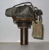
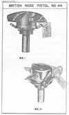
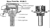
Available publications describe the subject Pistol as differing from the Mk II in several respects.
The vane cap (5 vanes) is retained by a new type of Safety Clip, the hook end of which locates in a hole in one of the Arming Vanes, while the plain end passes through the single hole in the vane cap and engages a safety-pin groove in the Pistol body.
The two Safety Pin holes in the Vane Cap and the four notches in the top edge of the body are omitted. The air pressure relief groove is diametrically opposite the Safety-Pin groove and extends from the top of the body to a point level with the top of the Safety-Pin groove.
This image CH12623 in the IWM Collection…….
…….appears to show three No 44 Pistols installed in a 4000 pound HC Bomb.
Reference 1 (below) describing the fuzing of a 4000 lb HC Bomb as fitting an appropriate pistol (with Safety Pin installed) and screwing it in hand tight. There is no fitting of a Fuzing Wire to lock the vanes implying the aircraft Fuzing Link is connected directly to the pistol’s built-in safety device, being a fork or clip dependent on pistol type.
Referring to my Para 1 (above), does anyone have a diagram or image of a No 44 Mk III Nose Pistol showing the arrangement of the Safety Clip?
Referring to the IWM Image, at which point on the Pistol was the aircraft Fuzing Link connected? Presumably, on the Mark III it would be to the new Safety Clip?
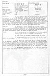
Reference 2 shows a diagram of a Mk II pistol fitted with a 'Locking ring' It is show with a tab which appears (to me) to be for a Fuzing Wire to pass through after also passing through a hole in a vane. This would lock the Vane Cap prior to release. If not, what is the purpose?
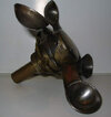
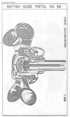
Ultimately, for the HC bomb series, the No 55 Mk 1 Nose Pistol was introduced. This is described as identical to the No 44 Mk III except that vane cap with four anemometer (cup type) vanes were fitted. I had, at one time seen an image of this fuze installed in a bomb but now cannot find one on-line. Can anyone please point me to a diagram or image?
With thanks.
Reference 1 - RAF Air Publication 1661B Vol 1. Ch 9 Aircraft Bombs
Reference 2 - US OP1665 British Explosive Ordnance Page 227
Available publications describe the subject Pistol as differing from the Mk II in several respects.
The vane cap (5 vanes) is retained by a new type of Safety Clip, the hook end of which locates in a hole in one of the Arming Vanes, while the plain end passes through the single hole in the vane cap and engages a safety-pin groove in the Pistol body.
The two Safety Pin holes in the Vane Cap and the four notches in the top edge of the body are omitted. The air pressure relief groove is diametrically opposite the Safety-Pin groove and extends from the top of the body to a point level with the top of the Safety-Pin groove.
This image CH12623 in the IWM Collection…….
…….appears to show three No 44 Pistols installed in a 4000 pound HC Bomb.
Reference 1 (below) describing the fuzing of a 4000 lb HC Bomb as fitting an appropriate pistol (with Safety Pin installed) and screwing it in hand tight. There is no fitting of a Fuzing Wire to lock the vanes implying the aircraft Fuzing Link is connected directly to the pistol’s built-in safety device, being a fork or clip dependent on pistol type.
Referring to my Para 1 (above), does anyone have a diagram or image of a No 44 Mk III Nose Pistol showing the arrangement of the Safety Clip?
Referring to the IWM Image, at which point on the Pistol was the aircraft Fuzing Link connected? Presumably, on the Mark III it would be to the new Safety Clip?
Reference 2 shows a diagram of a Mk II pistol fitted with a 'Locking ring' It is show with a tab which appears (to me) to be for a Fuzing Wire to pass through after also passing through a hole in a vane. This would lock the Vane Cap prior to release. If not, what is the purpose?
Ultimately, for the HC bomb series, the No 55 Mk 1 Nose Pistol was introduced. This is described as identical to the No 44 Mk III except that vane cap with four anemometer (cup type) vanes were fitted. I had, at one time seen an image of this fuze installed in a bomb but now cannot find one on-line. Can anyone please point me to a diagram or image?
With thanks.
Reference 1 - RAF Air Publication 1661B Vol 1. Ch 9 Aircraft Bombs
Reference 2 - US OP1665 British Explosive Ordnance Page 227