pzgr40
Well-Known Member
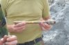
Cutaway model of a British tail fuze No.17. This fuze is a chemical time fuze with an anti removal device. The fuze is used in the 250 and 500 Lb GP bombs. With the old type of these bombs the fuze was placed in the tail cone of the bomb, causing many duds as the fuze bend during impact. With later types of these bombs the fuze was placed insuide the bomb body, leading to less duds.
The tail fuyze No.17 was a very complicated type of fuze , designed in such a way that it was safe until impact. It could not explode in the bomb bay of the plane , even if the glass bottle with aceton is broken, as there is no spring force on the firing pin. It could also be removed from the bomb body if the bomb was brought back to homebase (with a normal landing).
During WW2 however, with major losses to bombers en route -or back- to the target, this safety issue became less important, and the -complex and expensive to manufacture- tail fuze No.17 was replaced with the tail fuze No.37, that was less safe, but much easier and cheaper to manufacture.
Description and functioning of the fuze:
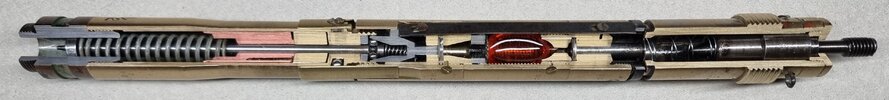
Parts:
1 - Inertia weight housing (brass)
2 - aft cover (brass)
3 - Inertia weight (steel)
4 - Spring (steel)
5 - resistance ring (red copper)
6 - Piston housing (brass)
7 - Piston (steel)
8 - piston (brass)
9 - ampoule housing (brass)
10 - ampoule (glass ampoule filled with aceton)
11 - Sift ring (hardened steel)
12 - distance piece (brass)
13 - filler ring (steel)
14 - celluloid disc (celluloid)
15 - release mechanism housing (brass)
16 - release piston (steel)
17 - spring (steel)
18 - filler ring (steel)
19 - balls (6x , steel)
20 - firing pin housing (brass)
21 - connection piece (steel)
22 - firing pin (steel)
23 - firing pin spring (steel)
24 - firing pin spring tensioning piston (red copper)
25 - radial fixating sleeve (brass)
26 - radial fixating sleeve inertia weight (brass)
27 - fixating screw (brass)
In safe position, the inertia weight (3) is fixated by the nut on the propeller (missing here) over the protruding threaded rod of the weight, kept in backward position. The red copper spring tensioning piston (24) is kept in backward position by the firing pin spring (23), which is not tensioned in the safe position. In this picture it is in armed position. The piston (24) also keeps the inertia weight (26) -connected to the radial fixating sleeve (25) by means of a fixating screw (27)- in backward position.
Functioning of the fuze.:
Upon release from the bomb rack, the safety wire of the propeller is withdrawn, allowing the propeller to unwind in the airstream. When the propeller falls away, the inertia weight (3) is free to move forward upon impact.
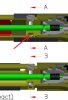
Upon impact three things happen simultanoiusly:
A – the inertia weight is swung forward against it’s spring (4),bending inward the red copper resistance ring (5), pushing the steel (7) and brass (8) piston forward, breaking the ampoule (10). The aceton starts dissolving the celluloid disc (14).
B – The firing pin tensioning piston (24) is swung forward by inertia, tensioning the firing pin spring (23). A small edge of the forward end of the piston is widened as it is forced over the chamfered edge on the back of the connection piece (21), fixating it in it’s forward position, keeping the firing pin spring tensioned.
C – The radial fixating sleeve inertai weight (26) moves forward , together with the radial fixarting sleeve (25), allowing the release mechanism housing (15) to rotate against the firing pin housing(20). This activates the anti removal device.
The aceton (10) starts to dissolve the celluloid disc (14) up to the moment it becomes so soft that the spring (17) inside the release piston (16) moves the piston upward, allowing the balls (19) to move outward, releasing the firing pin (20) to move downward into the firing cap of the detonator, exploding the bomb.
If any attempt is made to unscew the fuze from the bomb, unscrewing the release mechanism housing (15) against the firing pin housing (20), the spring (17) between the firing pin (22) and the release piston (16) will move the piston upward , allowing the balls (19) to move outward, releasing the firing pin, detonating the bomb.
This specific fuze has the marking “1/2” stamped in the firing pin housing, so I think it has a 0,5 hours delay.
Regards, DJH.
The tail fuyze No.17 was a very complicated type of fuze , designed in such a way that it was safe until impact. It could not explode in the bomb bay of the plane , even if the glass bottle with aceton is broken, as there is no spring force on the firing pin. It could also be removed from the bomb body if the bomb was brought back to homebase (with a normal landing).
During WW2 however, with major losses to bombers en route -or back- to the target, this safety issue became less important, and the -complex and expensive to manufacture- tail fuze No.17 was replaced with the tail fuze No.37, that was less safe, but much easier and cheaper to manufacture.
Description and functioning of the fuze:
Parts:
1 - Inertia weight housing (brass)
2 - aft cover (brass)
3 - Inertia weight (steel)
4 - Spring (steel)
5 - resistance ring (red copper)
6 - Piston housing (brass)
7 - Piston (steel)
8 - piston (brass)
9 - ampoule housing (brass)
10 - ampoule (glass ampoule filled with aceton)
11 - Sift ring (hardened steel)
12 - distance piece (brass)
13 - filler ring (steel)
14 - celluloid disc (celluloid)
15 - release mechanism housing (brass)
16 - release piston (steel)
17 - spring (steel)
18 - filler ring (steel)
19 - balls (6x , steel)
20 - firing pin housing (brass)
21 - connection piece (steel)
22 - firing pin (steel)
23 - firing pin spring (steel)
24 - firing pin spring tensioning piston (red copper)
25 - radial fixating sleeve (brass)
26 - radial fixating sleeve inertia weight (brass)
27 - fixating screw (brass)
In safe position, the inertia weight (3) is fixated by the nut on the propeller (missing here) over the protruding threaded rod of the weight, kept in backward position. The red copper spring tensioning piston (24) is kept in backward position by the firing pin spring (23), which is not tensioned in the safe position. In this picture it is in armed position. The piston (24) also keeps the inertia weight (26) -connected to the radial fixating sleeve (25) by means of a fixating screw (27)- in backward position.
Functioning of the fuze.:
Upon release from the bomb rack, the safety wire of the propeller is withdrawn, allowing the propeller to unwind in the airstream. When the propeller falls away, the inertia weight (3) is free to move forward upon impact.
Upon impact three things happen simultanoiusly:
A – the inertia weight is swung forward against it’s spring (4),bending inward the red copper resistance ring (5), pushing the steel (7) and brass (8) piston forward, breaking the ampoule (10). The aceton starts dissolving the celluloid disc (14).
B – The firing pin tensioning piston (24) is swung forward by inertia, tensioning the firing pin spring (23). A small edge of the forward end of the piston is widened as it is forced over the chamfered edge on the back of the connection piece (21), fixating it in it’s forward position, keeping the firing pin spring tensioned.
C – The radial fixating sleeve inertai weight (26) moves forward , together with the radial fixarting sleeve (25), allowing the release mechanism housing (15) to rotate against the firing pin housing(20). This activates the anti removal device.
The aceton (10) starts to dissolve the celluloid disc (14) up to the moment it becomes so soft that the spring (17) inside the release piston (16) moves the piston upward, allowing the balls (19) to move outward, releasing the firing pin (20) to move downward into the firing cap of the detonator, exploding the bomb.
If any attempt is made to unscew the fuze from the bomb, unscrewing the release mechanism housing (15) against the firing pin housing (20), the spring (17) between the firing pin (22) and the release piston (16) will move the piston upward , allowing the balls (19) to move outward, releasing the firing pin, detonating the bomb.
This specific fuze has the marking “1/2” stamped in the firing pin housing, so I think it has a 0,5 hours delay.
Regards, DJH.
Attachments
Last edited: