It seems tht there si a need for a few additional details to avoid misunderstandings on this issue:
The Vickers K in the RAF and RNAS was introduced to equip open-air single-gun turrets - the classic so called ("observer gun position" (Swordfish and such aircraft). These Vickers K were the regular model with the block and handle.
The single Vickers K gun installation in a closed turret was initially done using the Bristol "pedestal mounting":
View attachment 200819
The most common installation was a development of the former one, in the form of the Bristol B.I turret which equipped RAF Blenheim, and with some modifications the Australian Bleinheim and Beauforts.
The blenheim manual includes these lines when speaking of the upper turret::
"On the right handle was the Gun-firing Trigger, linked to the Gun by a Bowden Cable.
In later Versions, the Trigger operated Solenoid Units attached to the Guns. "
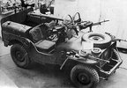
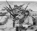
The following photographs are of the Australian installation - Pay attention to the way the vickers K is mounted, laying on its side, quite different from the Bleinheim turret instalation.
View attachment 200813View attachment 200814View attachment 200815View attachment 200816View attachment 200817View attachment 200818
Concerning double gun turrets installation, modifications appeared to be necessary:
The RAF document "AIR 41-82 SD 737 Armament Vol II Guns, Gunsights, Turrets, Ammunition and Pyrotechnics" includes the following lines:
"The Vickers ' K ' was accepted as a replacement for the Lewis gun on 11 February 1936, an experimental order for 200 being placed for Service trials.
The Vickers G.O. was to be used in turrets which were designed for single guns,
...
In order to increase the fire power for bomber defence a twin version of the Vickers G.O. gun was considered.
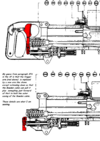
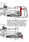
This twin gun, which was ready towards the end of 1938, consisted of two G.O. guns mounted on their sides with the feed openings outwards and ejection openings downwards.
The mounting yoke was replaced by a fitting which connected the two guns together, and the back blocks were replaced by a common back block connocting the two guns at the rear, and having a single gear mechanism.
In the left-hand gun the body and breech block were special parts and not interchangeable with the standard components.
The first trials with the gun were not very successful; it gave frequent ' caps out ', in spite of the modified ejector, and suffered a number of
breakages of minor components. After firing a considerable number of rounds, the gun was returned to Messrs. Vickers. Upon examination and fuller range tests, it was found that although originally the gun fired at 1,000 rounds per rninute, during the trials the speed had worked up to over 1,200 rounds per minute, and it was this high speed that was causing caps out · and the breakage of components. The gun was re-built by Vickers and a further trial carried out on the Army range at Hythe. The gas recoil system had been adjusted to keep the speed below 1,000 rounds per minute, and the gun fired 20,000 rounds without further trouble. At the end of this trial the bodies and back block had fired over 40,000 rounds and one body was still serviceable. The Air Staff were notified that the new Vickers G.O. gun was considered suitable for use in
the Service, but there were considerable delays in deciding whether the twin gun should be adopted.
Before a decision had been given, Bomber Command asked as a result of early operations, for two guns to be mounted on the rear cockpits of Hampden aircraft in place of the single gun. As, however, the production of the twin gun involved special tooling up, and consequent serious delays, it was decided, in view of the production position, to abandon further work on the twin gun.
As the war progressed, the aircraft fitted with Vikkers G.O. guns were gradually withdrawn from operational use, and replaced by aircraft equipped with Browning gun turrets.
By 1943, the Vickers G.O. gun was virtually obsolete in the Royal Air Force, although it continued to be issued in the Fleet Air Arm until the end of the war. A large number of guns rendered surplus to requirements were issued to the Army and Navy for ground use."
I hope this will help.