pzgr40
Well-Known Member
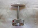
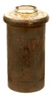
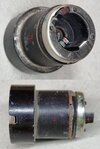
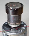
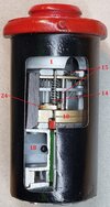
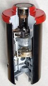
Cutaway model of a German WW2 Zt Z 89b (time fuze 89b), used in clustercontainers AB 250, AB 500 and AB 1000, as well as in the FA 50 photoflash bomb.
The Zt Z 89b is an electric activated mechanical clockwork fuze with a thermal plug safety to activate the clock and arm the firing pin.
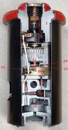
The fuze consists of three main parts, from top to bottom;
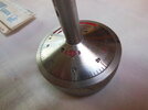
The mechanical clock (pict. 02, 03, 08) consists of a spring loaded reduction gear (10) that unwinds as the clock is released to run down. In top of the clock a rotating disc (11) is placed with a slot (12) and a notch (13). The notch hooks behind the notch of the rotary knob (4), allowing the rotating disc (11) to be rotated, thus setting time. the springloaded firing pin (14) is held in armed position by a springloaded lever (15) that wants to rotate inward but is prevented by the rotatable disc until the lever rotates into the slot (12), releasing the firing pin. In picture 05 one can see the whole mechanism as placed in the fuze.
The clockspring (pict 02) is placed in the large aluminium gearwheel (16) which is connected to the brass gearwheel (17) below it on the same shaft. This brass gearwheel powers the reduction gear (10) in the two brass discs below it.
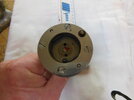
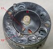
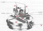
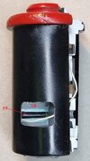
The safey mechanism (pict. 02, 06 and 07) consists of a cast zinc alloy housing (18) containing the thermal igniter (19) , the thermal plug (20) and the three springloaded plungers (21, 22 and 23). When the bomb is released, the electric pulse on the charging plate is passed through the charging rod, igniting the thermal igniter (19). This produces a flame that melts away the thermal plug (20), allowing the horizontal plunjer (21) to move sideways, releasing the plunger that blocks the geartrain (22) to move down, releasing the geartrain. The other plunger (23) moves down, releasing a springloaded slider (24) that rotates away from under the firing pin (14), arming the firing pin.
In short:
Diameter fuze body : 49 mm
Complete fuze length : 107 mm
Regards, DJH
The Zt Z 89b is an electric activated mechanical clockwork fuze with a thermal plug safety to activate the clock and arm the firing pin.
The fuze consists of three main parts, from top to bottom;
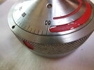
- The time setting mechanism (0 to 80 seconds), with the electric connector.
- The mechanical clock with the firing pin mechanism and the firing cap.
- The safety mechanism with the electrically ignited igniter, the thermal plug and the three safety plungers.
The mechanical clock (pict. 02, 03, 08) consists of a spring loaded reduction gear (10) that unwinds as the clock is released to run down. In top of the clock a rotating disc (11) is placed with a slot (12) and a notch (13). The notch hooks behind the notch of the rotary knob (4), allowing the rotating disc (11) to be rotated, thus setting time. the springloaded firing pin (14) is held in armed position by a springloaded lever (15) that wants to rotate inward but is prevented by the rotatable disc until the lever rotates into the slot (12), releasing the firing pin. In picture 05 one can see the whole mechanism as placed in the fuze.
The clockspring (pict 02) is placed in the large aluminium gearwheel (16) which is connected to the brass gearwheel (17) below it on the same shaft. This brass gearwheel powers the reduction gear (10) in the two brass discs below it.
The safey mechanism (pict. 02, 06 and 07) consists of a cast zinc alloy housing (18) containing the thermal igniter (19) , the thermal plug (20) and the three springloaded plungers (21, 22 and 23). When the bomb is released, the electric pulse on the charging plate is passed through the charging rod, igniting the thermal igniter (19). This produces a flame that melts away the thermal plug (20), allowing the horizontal plunjer (21) to move sideways, releasing the plunger that blocks the geartrain (22) to move down, releasing the geartrain. The other plunger (23) moves down, releasing a springloaded slider (24) that rotates away from under the firing pin (14), arming the firing pin.
In short:
- Before placing the bomb in the bomb rack, the desired time is -hand- set.
- The bomb is placed in the bomb rack, and the electric charging head is placed on the fuze, depressing the charging plate and arming rod, closing the electric circuit.
- Upon release, an electric pulse is passed, igniting the thermal igniter.
- The flame of the thermal igniter melts away the thermal plug, allowing both vertical plungers to be retracted, starting the clock and retracting the firing pin safety
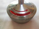
- The clockwork runs down and the until the springloaded arm moves into the slot of the rotating disc, releasing the firing pin into the firing cap (red). The flame travels through a series of channels (painted green) until it appears from the center hole in the lower portion of the fuze.
Diameter fuze body : 49 mm
Complete fuze length : 107 mm
Regards, DJH
Attachments
-
 01 - Zt.Z 89b .jpg60.6 KB · Views: 78
 -
 02 - Zt.Z 89b cutaway frontal.jpg980.9 KB · Views: 79
 -
 03 - Zt Z 89b clockwork.jpg953.5 KB · Views: 79
 -
 04 - Zt Z 89b setting wheel 2.jpg1.2 MB · Views: 73
 -
 05 - Zt Z 89b setting mechanism assembled.jpg832.8 KB · Views: 72
 -
 06 - Zt Z 89b melting safety1.jpg113 KB · Views: 74
 -
 07 - Zt Z 89b electric igniter.jpg1 MB · Views: 73
 -
 08 - Zt Z 89b firing pin mechanism.jpg1.1 MB · Views: 70
 -
 09 - Zt Z 89b angular view.jpg1 MB · Views: 77
Last edited: