British Ordnance Collectors Network
You are using an out of date browser. It may not display this or other websites correctly.
You should upgrade or use an alternative browser.
You should upgrade or use an alternative browser.
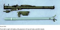
Strela-2 9M32 Missile SA-7 Grail
- Thread starter microplastic
- Start date
microplastic
Well-Known Member
thanks,
thats very helpful!
thats very helpful!
Weasel Pilot
Well-Known Member

Weasel Pilot
Well-Known Member
Picture from the example in the WTS in Koblenz
RedwireSolutions
New Member
Following would love to see blueprints of the warhead section. Im creating a 3d printable training aid
It does not contain a description and instructions, both in Russian and in Czech, it does not contain a description or a drawing of the function of the fuse or a more detailed drawing of the warhaed unit, fuse , it only lists the groups and briefly describes their purpose, nothing else.
The PL system 9M 32M was produced by the Czechoslovakia, Poland, Yugoslavia, ... under license.
The number of countries to which Russia exported it is close to 60 countries in the world.
Data on the export of countries that produced under license is unknown.
The PL system 9M 32M was produced by the Czechoslovakia, Poland, Yugoslavia, ... under license.
The number of countries to which Russia exported it is close to 60 countries in the world.
Data on the export of countries that produced under license is unknown.
microplastic
Well-Known Member
Not easy to get informations for the strela, here are some results of the internet:
here are some informations for the igla, some parts are the same as used in the strela: https://studopedia.ru/1_56193_rulevoy-otsek.html
the strela 9M32M was also used in former GDR (Germany), but it is hard to obtain those german manuals, I've never seen one.
BTW, the german strelas were delivered to Ukraine...
Attachments
Hi Akon,Hi all
How do you solve the warhaed part of the rocket and the fuse ?
Akon
I am sending you some information about the Strela S-2M system.


Best regards
BrunO
The description of the operation of the 9N15M warhead and the 9E22M SAM is as follows:Hi all
How do you solve the warhaed part of the rocket and the fuse ?
Akon
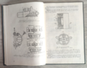
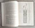
The complete 9N15M warhead consists of a warhead and a 9E22M fuze (Safety Arming Mechanism). The warhead has a fragmentation, blasting and cumulative effect on the target.
The warhead consists of a body (1), which has a protrusion (a) with a hole for the rocket launcher's fixation latch. Furthermore, the warhead contains an explosive charge (2), a buster (3) and a tube (27) through which electrical wires pass from the SAM to the rudder control device. The electrical wires serve to supply electrical voltage to the electric squib (29) and capacitor C1 (11) of the SAM.
The SAM is designed to initiate the warhead upon impact of the missile with the target or to self-destruct the missile. The SAM is electromechanical, impact-type with a self-destruct mechanism.
The SAM has two levels of locking that are only released in flight, ensuring the missile's safety during launch, storage and transport.
The SAM consists of a safety, detonation and self-destruction mechanism, impact switch and mounting panel.
The safety mechanism is designed to ensure safety during handling and in flight until the moment of unlocking. It consists of a case (30) with an electric squib (29), a rotating insert (5) with a combined electric detonator (33), a resistor R3 (34), a contact group KP3 (32, 41), an inertial pin (20) with a spring (19) and a case (18). In the rotating insert (5) there is a resistor R3 (34) and a clip (36), fixed with a rivet (35). The contact group KP3 consists of two pairs of slats (32, 38) and contacts (40, 41). One pair of slats (32) is fixed to the rotating insert (5) with the help of screws (31) and the second pair of slats (38) is fixed to the rotating insert with the help of a shorting pin (37). The slats are connected to each other. Resistor R4 (28) is soldered to contacts (41). The rotating insert (5) rests on the heel bearing (22) and is under the constant effect of the torque of the spring (21). he spring (21) constantly tries to rotate the rotating insert (5) on the shaft (4) counterclockwise.
The rotating insert (5) is held in a locked position by a blocking pin (6), pressed with the help of a spring (8) against the pyrotechnic safety catch (7) and with the help of a inertia pin (20). The detonating mechanism is intended for initiating the warhead and consists of a relay charge (25) pressed into a relay charge case (26). The relay charge case (26) is pressed into the lid (24). The lid (24) is screwed into the body of SAM (23). The self-destruction mechanism is designed to destroy the missile after a flight time of 14 - 17 seconds and consists of a self-destruction ring (10) with a pressed-in pyrotechnic composition (9).
The self-destruct ring (10) is covered from above with cardboard and also with a cloth backing. The self-destruct mechanism is pressed against the housing (39) with the help of a pressure ring. The impact switch is designed to connect the circuits of the combined electric detonator (33) upon impact with the target. It consists of a housing (50), pressed against a magnet (53) with the help of a ring (52) and frame (45), and a contact group KP1. The KP1 contact group consists of an anchor (51) and four slats in an insulating sleeve (49), fastened with screws (48). The magnet (53) is mounted on the flange (54) and pressed against it with the help of the grounding (45). The frame (45) is screwed on one side to the flange (54) and on the other side it rests on the ring (52). The anchor (51), into which the core (46) is screwed, serves to adjust the tear-off force and is a movable element of the impact switch. As the missile rotates in flight, it is held in the retracted (locked) position by the force of the magnet. The pulse generator coil (44) consists of a frame (45) and a pulse generator winding. The winding terminals are installed in the panel (43). The impact switch is fixed in the SAM body (23) with the help of a nut (42). The mounting panel (15) houses the SAM elements, diode D, capacitor C1 (11), transistor (PP), resistors R1 and R2, and interconnecting electrical wires. The assembled panel (43) is cast in insulating material.
The KP2 contact group is mounted on the mounting panel (15) with the help of four screws (17). The KP2 contact group consists of a lid (13) and a lid (14), mutually insulated by a washer (12). All mechanisms are located in the SAM body (23), which is covered by a sleeve (16).Hi all
How do you solve the warhaed part of the rocket and the fuse ?
Akon
The SAM electrical scheme consists of a unlocking, fire and control circuit. The unlocking circuit is connected to the safety capacitor C2, which is located in the rocket's rudder section and contains an electric squib. The voltage from the capacitor is supplied to the electric igniter after the missile has left the launcher, the rudders have been opened and the contacts of the V1 switch of the rocket terminal box have been connected.
The fire circuit diagram includes: diode D, capacitor C1, contact groups KP1, KP2, KP3, pulse generator IG, transistor PP, which amplifies the signal from the pulse generator, and a ED-DD combined electric detonator.
To protect against static electricity, in case of bridge overload, the electric combination detonator ED-DD is connected laterally using resistor R3. To discharge capacitor C1 during checks, the diode is bridged sideways using resistor R1. To limit the collector current of the transistor PP, in the case of a pulse generator coil voltage IG, the coil is bridged laterally with the help of resistor R2. To check the disconnection of contacts KP1, KP2 and to check the connection of the collector-emitter circuit of transistor PP, resistor R4 is connected. The contact circuit (contacts 1 and 4) is used to check whether the SAM is not unlocked and is secured by creating a circuit between contacts 4-8 and 3-7 of the KP3 contact group. The SAM and the warhead are activated after firing as follows:
After pressing the trigger of the 9P58 launcher, a voltage of 40 volts is applied to the safety capacitor C2 (in the rudder section) through the resistor R2. As soon as the missile leaves the launching tube after launch, the rudders are opened, the contacts of the switch V1 are connected and a voltage of 40 volts is applied to the SAM capacitor C1 from the on-board power supply, and the voltage of the capacitor C2 initiates the electric squib (28), which simultaneously ignites a composition in pyrotechnic safety catch (7) and a composition in the self-destruct ring (10).
At the same time, the inertia pin (20), due to the inertial force of the axial acceleration, is pressed downwards and frees the way for the rotating insert (5) to rotate. This removes the 1st level of SAM security. After the missile moves away from the launchering tube, the inertia of the force acting on the inertia pin (20) decreases and it begins to move upwards. At this stage, the inertia pin blocks the rotation of the rotary insert (5), preventing the SAM electrical circuit from closing.
When the missile flies a distance of 80 - 250 m from the launcher tube, the pyrotechnic safety catch (7) burns out and clears the way for the blocking pin (6). Under the action of the spring (8), the blocking pin (6) is pushed out of the rotating insert (5) and, under the action of the spring (21), it is rotated into the fire position. The second level of SAM security is now removed. The SAM is fully arming and ready for operation. The rotating insert (5) is rotated under the action of the spring (21) so that the axis of the combined electric detonator ED-DD (33) is aligned with the axis of the relay charge (25). The lower front wall of the combined electric detonator ED-DD (33) is positioned opposite the end of the pressed pyrotechnic composition of the self-destruction ring (10) and the combat circuit of the combined electric detonator ED-DD (33) is closed with the help of the slats (32, 38) and contacts (40, 41) of the contact group KP3. During the flight, the pyrotechnic composition (9) of the self-destruct ring (10) burns. The on-board power supply during the missile's flight powers the SAM firing circuit's power capacitor C1(11). When the missile hits the target, the achor (51) closes, is torn away from the magnet (53) by inertial forces, and moves towards the slats (47). n this case, an electromotive force is induced in the coil of the pulse generator (44), the resulting current is amplified by the transistor PP and fed to the combined electric detonator ED-DD (33). The combined electric detonator ED-DD (33) is thus activated. The combined electric detonator ED-DD (33) detonates the relay charge (25), which causes the booster (3) and then the explosive charge (2) to explode. The detonation of the explosive charge causes the walls of the warhead body (1) to rupture into fragments that act on the target in a radial direction with a blasting and fragmentation effect. In the axial direction, a cumulative beam is created, which breaks up groups and components of the missile's forward-mounted devices and directs them in a bundle of fragments towards the target, thereby causing additional destruction of the target. n case of a failure of the pulse generator IG or transistor PP in the SAM, there are two spare circuits for transmitting an electrical pulse to initiate the combined electric detonator ED-DD.
The first circuit : The closing anchor(51) when moving the joints of the slats (47) of the contact group KP1 and the current pulse from the capacitor C1 (11) is supplied to the combined electric detonator ED-DD (33).
The second circuit: When the SAM is destroyed, the cover (13) and the cover (14) of the contact group KP2 are connected. The electric current pulse from the capacitor C1 (11) is thus fed to the combined electric detonator ED-DD (33).
After a period of 14 - 17 seconds, the reinforcing pyrotechnic composition (9) in the self-destruction ring (10) burns out and the combined electric detonator ED-DD (33) is initiated by the flame discharge.
Hi BrunO
Thank you for the provided drawings and descriptions of the function.
The standard prescription no contains such a drawing.
For a long time I was not clear about how it functions and what it consists of, and thanks to you it has improved")
Akon
-------
Cit : Mimochodem trhavina A-IX-1O to písemeno na konci je ,,O,, je tj. Oxizin , případně A-IX-2O opět není číslovka ale 2 a písmeno ,,O,, .
Originál ruský má šablonaci trhaviny na bojové části jinou tj. Okf. , nebo případně ještě jiné typy ....
U pozice 3 -booster ruský zdroj uvádí Tetril. v licenčí výrobě ČSR je to flegm. pentrit .
Thank you for the provided drawings and descriptions of the function.
The standard prescription no contains such a drawing.
For a long time I was not clear about how it functions and what it consists of, and thanks to you it has improved
Akon
-------
Cit : Mimochodem trhavina A-IX-1O to písemeno na konci je ,,O,, je tj. Oxizin , případně A-IX-2O opět není číslovka ale 2 a písmeno ,,O,, .
Originál ruský má šablonaci trhaviny na bojové části jinou tj. Okf. , nebo případně ještě jiné typy ....
U pozice 3 -booster ruský zdroj uvádí Tetril. v licenčí výrobě ČSR je to flegm. pentrit .
Last edited:
microplastic
Well-Known Member
Hi Bruno,
thank you for the detailed informations, very helpfull !!!
thank you for the detailed informations, very helpfull !!!
Nazdar AKON,Hi BrunO
Thank you for the provided drawings and descriptions of the function.
The standard prescription no contains such a drawing.
For a long time I was not clear about how it functions and what it consists of, and thanks to you it has improved
Akon
-------
Cit : Mimochodem trhavina A-IX-1O to písemeno na konci je ,,O,, je tj. Oxizin , případně A-IX-2O opět není číslovka ale 2 a písmeno ,,O,, .
Originál ruský má šablonaci trhaviny na bojové části jinou tj. Okf. , nebo případně ještě jiné typy ....
U pozice 3 -booster ruský zdroj uvádí Tetril. v licenčí výrobě ČSR je to flegm. pentrit .
čo sa týka chemického zloženia trhaviny A-IX-20 čs. výroby, vždy som si myslel, že je to percentuálny pomer flegmatizovaného RDX (A-IX-10)/AL - (80/20). Keď sa pozrieš na hore uvedenú technickú špecifikáciu, nikde nevidíš písmeno "O". Všade uvidíš evidentne číslicu "0". Tým nechcem tvrdiť, že tam ten OXIZÍN nie je ale indexy trhavín A-IX-10 a A-IX-20 hovoria jasnou rečou.
Hi AKON,
regarding the chemical composition of the A-IX-20 explosive of Czechoslovak production, I always thought that it was the percentage ratio of phlegmatized RDX (A-IX-10)/AL - (80/20). When you look at the technical specification above, you don't see the letter "O" anywhere. You will obviously see the number "0" everywhere. I don't mean to say that the OXIZINE is not there, but the indices of the A-IX-10 and A-IX-20 explosives speak for themselves.


Hi Bruno
Výbušnina v ruském originále je označena: A-XI-I, možný jiný název je Octogen, česky se píše jako: A-XI-1, rozhodně neobsahuje žádný Hexogen, ale Octogen. Anglická zkratka pro Octogen je HMX. Nejedná se o směsnou výbušninu (A-XI-I), protože obsahuje výbušninu Octogen + vosk 5 % (z důvodů flegmatizace). Jednou obrovskou výhodou Octogenu je, že snese tepelné zahřátí až do 220 stupňů... což je výhodné pro střely. Je však dražší. A-XI-1 je ruská výbušnina z doby kolem let 1940-1941. Také mě zajímala, myslel jsem si, že jde o poválečný vývoj. Všechny vojenské zdroje o ní mlčí, nebo si to pletou... Pak dodám literaturu, která to potvrdí z více zdrojů (ruských) spíše než českých.
pro jistotu
Trhavina v ruském originále je označena : A-XI-I případný další název je Oktogen v češtině psáno jako: A-XI-1 určitě totálně žádný Hexogen nýbrž Oktogen.
Anglická zkratka Oktogenu je HMX .
Není to směsná trhavina (A-XI-I ) protože obsahuje POUZE JEDNU trhavinu Oktogen + vosk 5% (z důvodů flegmatizace )
Jedná se o obrovskou výhodu Oktogenu je ,že vydrží termický ohřev až do 220 stupňů ...což u raket je výhodnější .Ovšem je dražší .
A-XI-1 je to Ruská trhavina sahající do roku cca 1940-1941 .Taky mně to zaujalo měl jsem za to , že to je poválečný vývoj . Všechny vojenské zdroje o tom mlčí , a nebo do toho dávají zmatek ... Bohužel jsem na tom byl stejně jako ty než jsem šel do ruské litaratury ...a zjistil ten zmatek.
Pokračování příště o A-XI-1O , a potom sem dám odkaz na zdroje a výřezy, které to potvrzují z více zdrojů bude (Ruská) né česká
Akon
Last edited:
OK)))Hi Bruno
Výbušnina v ruském originále je označena: A-XI-I, možný jiný název je Octogen, česky se píše jako: A-XI-1, rozhodně neobsahuje žádný Hexogen, ale Octogen. Anglická zkratka pro Octogen je HMX. Nejedná se o směsnou výbušninu (A-XI-I), protože obsahuje výbušninu Octogen + vosk 5 % (z důvodů flegmatizace). Jednou obrovskou výhodou Octogenu je, že snese tepelné zahřátí až do 220 stupňů... což je výhodné pro střely. Je však dražší. A-XI-1 je ruská výbušnina z doby kolem let 1940-1941. Také mě zajímala, myslel jsem si, že jde o poválečný vývoj. Všechny vojenské zdroje o ní mlčí, nebo si to pletou... Pak dodám literaturu, která to potvrdí z více zdrojů (ruských) spíše než českých.
pro jistotu
Trhavina v ruském originále je označena : A-XI-I případný další název je Oktogen v češtině psáno jako: A-XI-1 určitě totálně žádný Hexogen nýbrž Oktogen.
Anglická zkratka Oktogenu je HMX .
Není to směsná trhavina (A-XI-I ) protože obsahuje POUZE JEDNU trhavinu Oktogen + vosk 5% (z důvodů flegmatizace )
Jedná se o obrovskou výhodu Oktogenu je ,že vydrží termický ohřev až do 220 stupňů ...což u raket je výhodnější .Ovšem je dražší .
A-XI-1 je to Ruská trhavina sahající do roku cca 1940-1941 .Taky mně to zaujalo měl jsem za to , že to je poválečný vývoj . Všechny vojenské zdroje o tom mlčí , a nebo do toho dávají zmatek ... Bohužel jsem na tom byl stejně jako ty než jsem šel do ruské litaratury ...a zjistil ten zmatek.
Pokračování příště o A-XI-1O , a potom sem dám odkaz na zdroje a výřezy, které to potvrzují z více zdrojů bude (Ruská) né česká
Akon
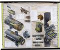
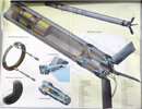
Ahoj AKON. Čo sa týka, trhaviny OKFOL v PLRS sovietskej konštrukcie, mám osobné skúsenosti zatiaľ iba s PLRS 9M39 "Igla", ktorú máme vo výzbroji. Neviem, ako to bolo u jej predchodcov S-2, S-2M, S-3 a Igla-1. V prílohe Ti posielam niekoľko snímkov z delaborácie bojovej časti 9N312F . V tejto bojovej časti sú nalaborované 3 základné trhaviny. Hlavná trhavina OKFAL-20 (OKTOGÉN/HLINÍK - 80/20) - 310 g, trhavina PETN v počinovéj náplni a v prenosnej trubke - 36 g a trhavina OKFOL-3,5 vo výbušnom generátore.Ahoj Bruno .Prekerni preklep : A-IX-1 a napisu hloupost typu A-XI-1 . opravy textu nejdou
Hi AKON,
as for OKFOL explosive in Soviet designed PLRS, I have personal experience so far only with the PLRS 9M39 "Igla", which we have in service. I do not know how it was with its predecessors S-2, S-2M, S-3 and Igla-1. In the attachment I am sending you some pictures from the delaboration of the 9N312F warhead. There are 3 basic explosives in this warhead. The main explosive OKFAL-20 (OCTOGEN/ALUMINUM - 80/20) - 310 g, PETN explosive in the booster and in the relay tube - 36 g and OKFOL-3.5 explosive in the explosive generator.

The 9N312F warhead with the 9E249 SAM

The 9E249 SAM

The 9Kh316 explosive generator

The main explosive OKFAL-20

The explosive PENT in the booster

The OKFOL-3,5 in the explosive generator
By the way, Igla is celebrating a small anniversary in the Slovak army this year.

Best regards
BrunO