British Ordnance Collectors Network
You are using an out of date browser. It may not display this or other websites correctly.
You should upgrade or use an alternative browser.
You should upgrade or use an alternative browser.
BOCN Guess what it is
- Thread starter spotter
- Start date
pointblank0
BOCN Supporter
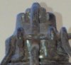
German M17 friction fuze?
pointblank0
BOCN Supporter
Head of an 84mm HEAT round?
pointblank0
BOCN Supporter
Ok, here we go
pointblank0
BOCN Supporter
Well that was quick. Yes an ARGES HG78


...and the paint didn't have time to dry.
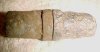
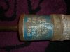
For the grenade anaraks the one in the picture is the No 68 Mk I first pattern with a Bakelite securing screw holding on the gas check plate (the idea being that it fractured on discharge allowing the plate to fall away and the fins to have a clear run of air). The Bakelite screw often broke during transport making it a nuisance to load the grenade in the discharger. In any case the ballistics of the grenade were not much altered by the fixing of the plate during flight so a No 68 Mark I second pattern was devised utilising a brass screw to keep the plate fixed in place.
Over to you Tom.
Thank you, Norman.
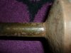
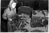
Something slightly different. The attached photo is one from a sequence of 3" munitions manufacturing (a British factory, 1942). What exactly are the items in the oblong trays being examined by the lady here?
Norman - please give a couple of others the chance to fire away first")
Tom.
Something slightly different. The attached photo is one from a sequence of 3" munitions manufacturing (a British factory, 1942). What exactly are the items in the oblong trays being examined by the lady here?
Norman - please give a couple of others the chance to fire away first
Tom.
Attachments
paul the grenade
Well-Known Member
i think its the inside core mould for the 3inch mortar
Related to what US-Subs has said, the half round lighter colored part on the table appears to be the sand core that would form the cavity for the explosive inside the projectiles. The metal would be cast around them, and then the sand would be washed out once the metal was solidified.
The woman is actually making up the cores at this point in the manufacturing process. The cores will go to another area to be inserted in the larger projectile mold.
The woman is actually making up the cores at this point in the manufacturing process. The cores will go to another area to be inserted in the larger projectile mold.
Last edited:
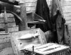
It is indeed part of the casting mold, but what exactly is the part (or what does it do)?
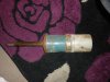
It's the core. It creates the cavity within the article being cast. Attached shows one standing vertically next to a casting box.
US-Subs was almost certainly about to come out with that detail, but Paul, you pipped him so over to you.
... and Hazord. Perfect description of the process. Thanks.
Attachments
Last edited: